Design
It was challenging to fit all our sensors into our circuit boards since we wanted a 20cm diameter robot, while keeping double layered wheels, double dribblers and a solenoid, which took up a lot of space. Here, we detail some design considerations for cramming our sensors and components in a small area.
Components
More details about the selection process can be found here.
Components List
| Component | Cost (SGD) |
|---|---|
| Layer 1 | |
| JMP-BE-3561 Motor × 4 | $480 |
| 1040B Solenoid | $5 |
| VNH5019A Motor Driver × 4 | $8 |
| ALS-PT19 Phototransistor × 40 | $4 |
| PMW3360 Mouse Sensor | $10 |
| Layer 2 | |
| Revolectrix 3S Battery | $20 |
| XA2212 820KV BLDC × 2 | $20 |
| Layer 3 | |
| Teensy 3.5 | $50 |
| STM32F103CBT6 × 2 | $6 |
| Adafruit NXP Precision IMU | $25 |
| Raspberry Pi 3B | $45 |
| Raspberry Pi Camera V1 | $3 |
| HC-05 Bluetooth Module | $5 |
| Hobbywing ESC × 2 | $20 |
| Layer 4 | |
| VL53L1X TOF × 4 | $30 |
| WS2812B Neopixel × 16 | $2 |
| Others | |
| Carbon Fiber | $26 |
| PCB (4 plates) | $25 |
| Assorted Parts | ≈$60 |
| Total | ≈$850 |
Positioning
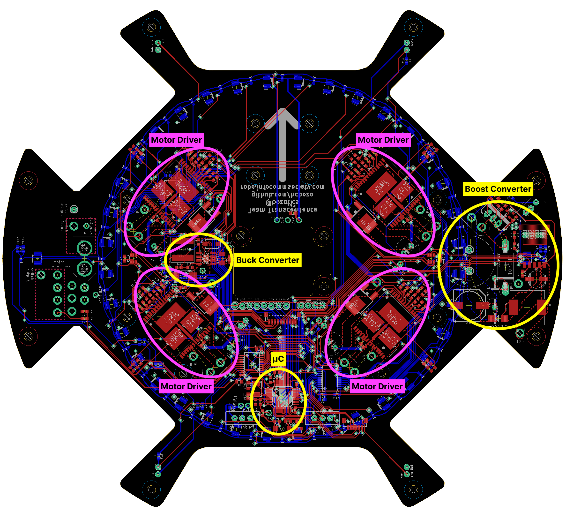
While designing our PCB, we made sure to position “groups” of components close to each other. e.g. resistors for motor drivers are placed together with the driver. This ensured that traces for related parts did not run all over the circuit board, and simplified the designing process.
We also ensured that these groups were placed close to the intended “destination”, e.g. the motor drivers were placed directly under the motors. This shortens cable runs and also ensures high current cables from the motors do not affect other data lines.
Lastly, we ensured that the boost converter circuit, a very high powered circuit charging capacitors at up to 60v, was placed far away from our other components to prevent any accidents or interference from the switching action of the boost converter.
Trace widths
A major issue with our initial circuit boards were the trace widths. We used the same thin trace width for everything from data lines to motor power, which is a really bad idea since ≈10A of current were running down traces rated for ≈0.8A.
Now, we utilise polygons / pours and thicker trace widths (40 mils) for our high current traces e.g. motor and solenoid.
High current traces running parallel to high speed signals or analog signals (from light sensors) can cause interference. This is especially so since we wanted to keep to a 2-layer PCB, meaning we could not rely on internal layers to separate data and power traces. Hence, to decrease the number of power traces throughout the PCB, high power lines are run through 18AWG wires.
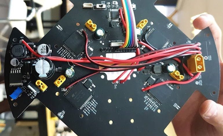
Although it looks ugly, it results in a more reliable circuit board as sudden braking / changing direction of the motor which causes a current spike will not affect surrounding analog circuits or interfere with communication signals.
Reference Schematics
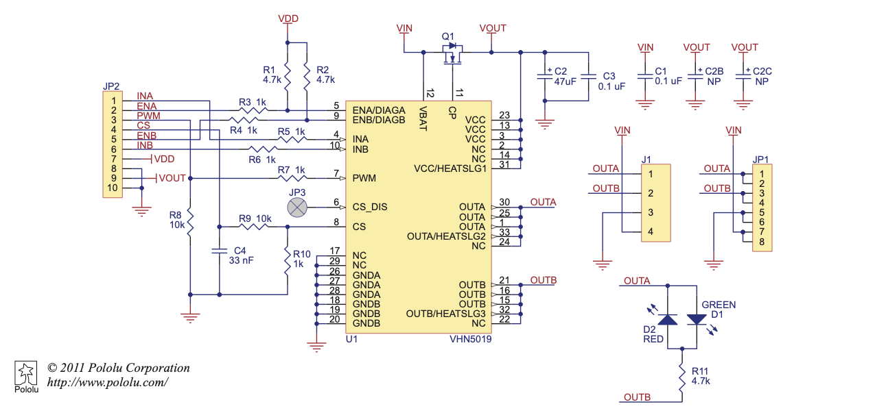
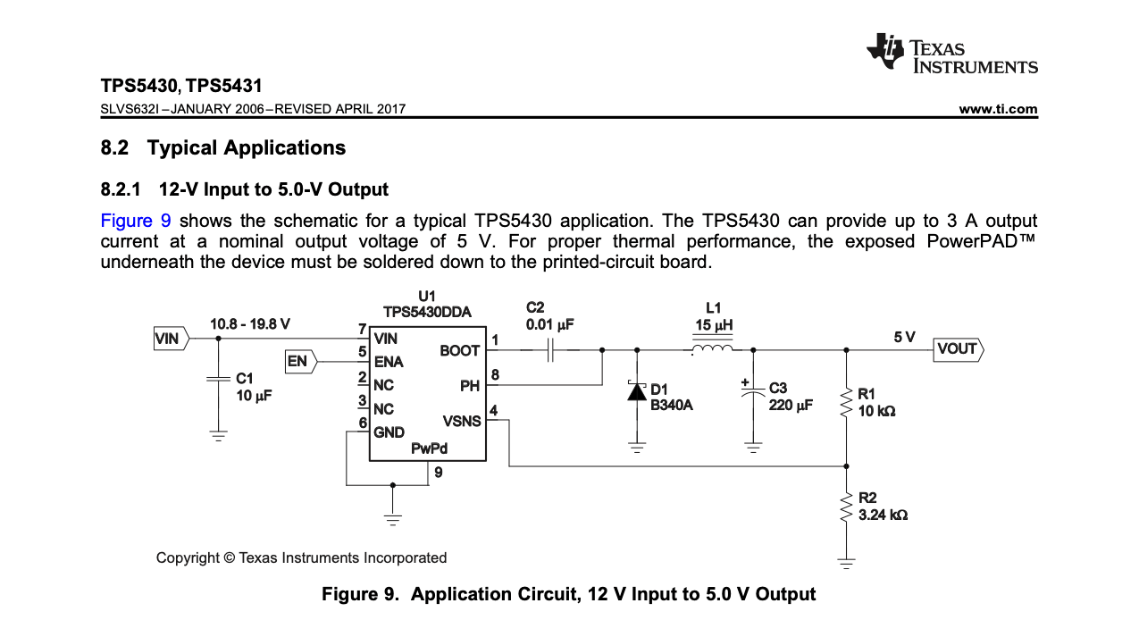
When we first shifted away from commercial off the shelf (COTS) components and breakout boards of ICs, we consulted the datasheets which contain a “recommended application schematic” most of the time, and simply use those to design our circuits.
Sometimes, these COTS components we purchase from Taobao come with schematics as well, and if we are using the same IC (which we usually are) we consult these schematics to design our circuits as well.
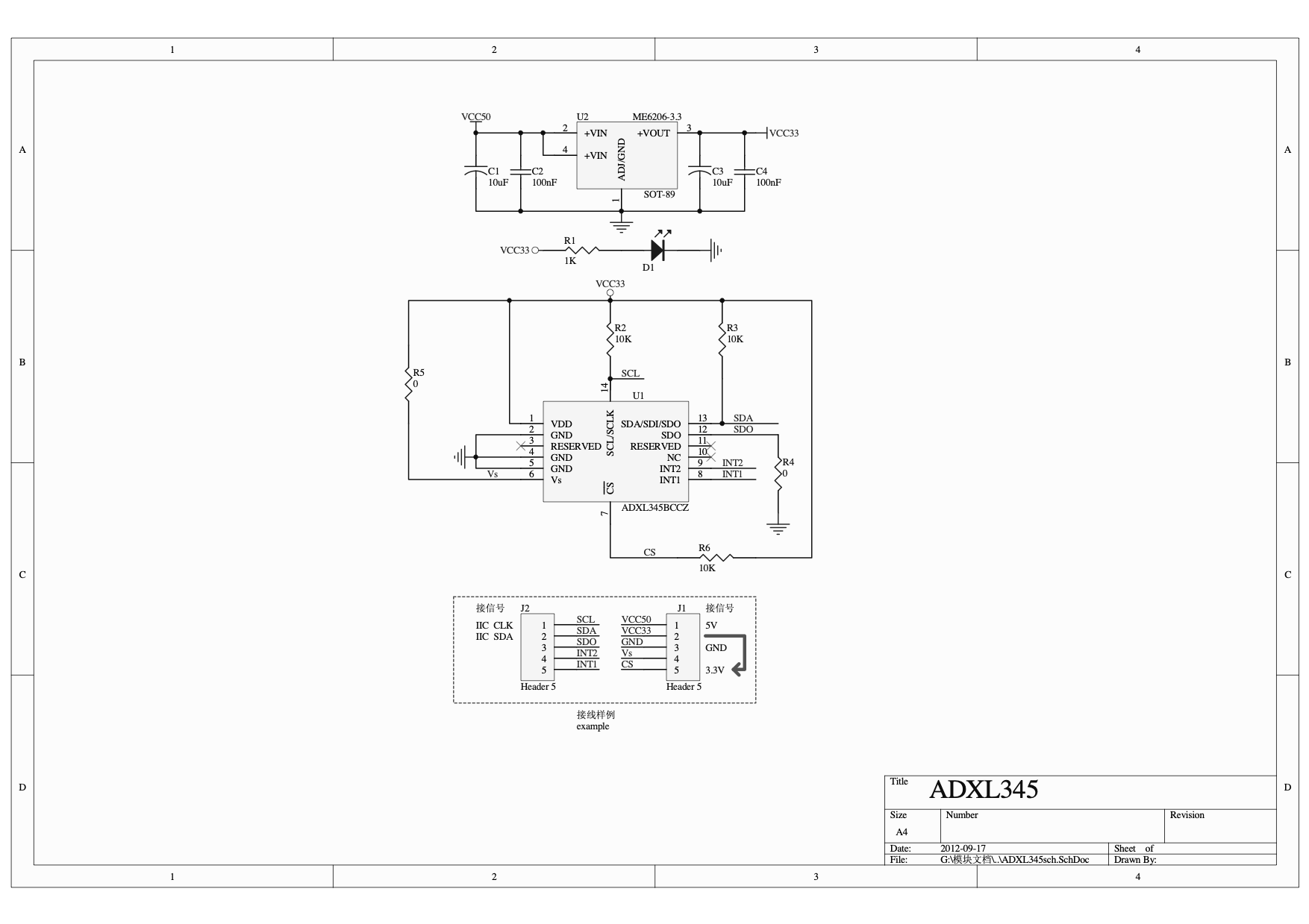
Lastly, ICs we use are typically found in COTS components from popular manufacturers like Sparkfun or Pololu, and these companies usually release their schematics, hence we can take those as reference when designing our circuits.