Components
After much consideration we have decided on the following components to be used in our circuit boards.
| Component | Cost (SGD) |
|---|---|
| Layer 1 | |
| JMP-BE-3561 Motor × 4 | $480 |
| 1040B Solenoid | $5 |
| VNH5019A Motor Driver × 4 | $8 |
| ALS-PT19 Phototransistor × 40 | $4 |
| PMW3360 Mouse Sensor | $10 |
| Layer 2 | |
| Revolectrix 3S Battery | $20 |
| XA2212 820KV BLDC × 2 | $20 |
| Layer 3 | |
| Teensy 3.5 | $50 |
| STM32F103CBT6 × 2 | $6 |
| Adafruit NXP Precision IMU | $25 |
| Raspberry Pi 3B | $45 |
| Raspberry Pi Camera V1 | $3 |
| HC-05 Bluetooth Module | $5 |
| Hobbywing ESC × 2 | $20 |
| Layer 4 | |
| VL53L1X TOF × 4 | $30 |
| WS2812B Neopixel × 16 | $2 |
| Others | |
| Carbon Fiber | $26 |
| PCB (4 plates) | $25 |
| Assorted Parts | ≈$60 |
| Total | ≈$850 |
Microcontrollers (µC)
Main µC
We use a Teensy 3.5/6 as a main µC due to its fast processing speed, large number of peripherals and I/O (but not too much so the overall size was still small), extensive support on Arduino IDE, and ease of reuse in the future as it was on a breakout board.
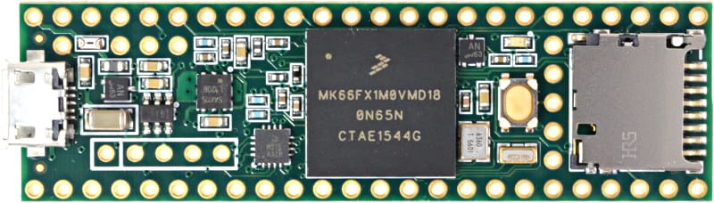
We chose the Teensy over other 32-bit µCs such as the Arduino Due, ST’s Nucleo lineup, etc because of its small size and good Arduino IDE support. We also wanted it to be on a breakout board as it was expensive, so soldering something like a STM32F4 directly onto our PCB was not a solution.
We are looking at the newer Teensy 4.0/1 µCs, however we are unlikely to switch away as we do not require that much speed and it is quite expensive to replace.
Sub-µC
We use multiple STM32F103CBT6 as sub-µCs to process sensor data (e.g. sensor fusion for our IMU) to not slow our main processor down and allow more tasks to be run parallel to each other.
We chose this IC in particular because we used it before on a Maple Mini, and the schematics for that are simple enough to understand. Also, it has extensive support from the Arduino STM32 Core, and it has a very cheap price (cheaper than the popular ATMEGA328P on Taobao!)** so we could solder it down directly without a breakout board.
We did consider other alternatives such as NXP’s Freescale (since the Teensy also used this) and Microchip’s ATSAMD (since it had good Arduino support) lineups. However, the lack of availability and the very low price of the STM32s on Taobao pulled us in that direction instead.
However, the STM32F103 is quite annoying to solder with the QFP package (we have broken a few legs before) and we do not saturate the I/O anyways. We are looking to shift towards smaller µCs with TSSOP packages in the STM32F0 series, and with that shift away from the Arduino ecosystem.
**Note: As of June 2021, due to the global chip shortage, prices for our STM32 chip have skyrocketed by almost 10x its original price, so this statement is not true anymore.
Programmers
To program the STM32s, we use J-Link OB boards from Taobao.
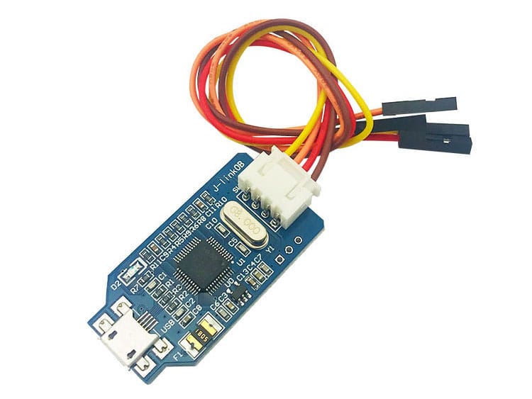
They were the best choice since J-Link Edu Mini / Black Magic Probe boards were not sold locally, and real ST-Links were significantly more expensive locally. We also wanted to be able to program chips other than STM32s in the future, hence we preferred the flexibility of J-Links over STLinks.
Currently, we use SH1.0 ports to connect the programmers to the PCB to save space. We have 6 pins: 3v3, GND, SWDIO, SWCLK, TX, RX. In the future, we would like to replace the TX/RX with SWO pins to fully utilise peripherals of the ARM ecosystem and not waste a UART, or even use the Real Time Transfer (RTT) feature available on J-Links to save on pins since the RTT can work through SWDIO.
Motor Drivers
DC Motor Drivers
We use 4 VNH5019A motor drivers to control our motors because it had a high current limit, low Rds(on) so there is minimal heat output, and it had a 3.3v voltage level. Since we had used the VNH2SP30 motor driver previously, and these two have similar architectures, we were confident that the motor driver would work well.
However, we (very recently) discovered that the VNH5019 coasts (leaves the switches off) rather than brakes (turns all the switches on to short the terminals) at every “0” in the PWM duty cycle. So far, we have not faced any issues with this implementation, but Texas Instrument’s DRV line could be considered if any problems come up.
BLDC ESC
We use 2 HobbyWing SkyWalker 30A ESCs for our dribbler BLDC motors. We use these due to the high current limit and cheap price from Taobao.
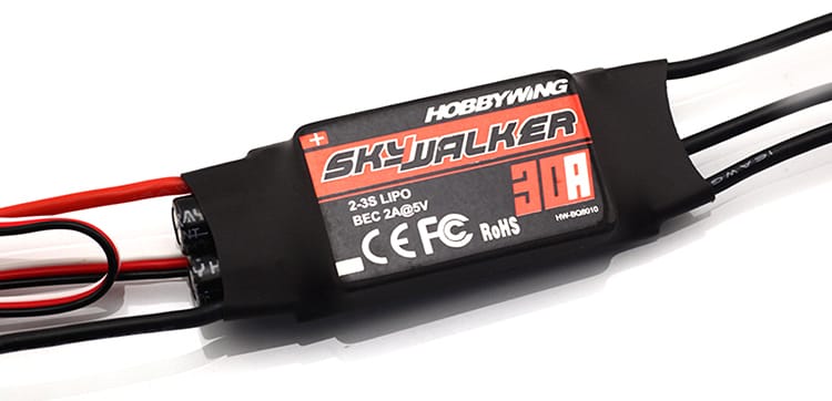
However, from our testing our dribbler rarely draws more than ≈2A of current. In the future, smaller and lighter ESCs can be used. We have been testing small HSKRC BLHeli_S ESCs, however as we did not want to waste the ESCs we already had we still use the large HobbyWing ESCs.
A note of caution: both these ESCs were annoying to control. They both required 5v logic levels, the HobbyWing one needed 50Hz Servo signals, and there was an initialisation sequence that lasts for ≈3s before the motors can actually turn on. The BLHeli_S one was also complex as we needed to understand and implement the OneShot125 protocol. We tried using the DShot protocol to no avail.
Sensors
IMU / Compass
We use the Adafruit NXP Precision IMU because of its accuracy and relatively cheap price. It was also very stable from our testing, something our past IMU used have struggled with.
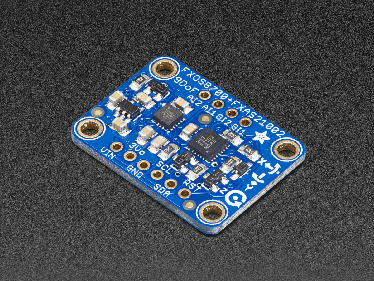
However, one downside compared to the popular BNO055 is the lack of a controller in-built to process sensor fusion algorithms. Hence, we dedicate one sub-µC solely to IMU sensor fusion tasks to ensure maximum stability and data rate.
Mouse Sensor
We use the PMW3360 on our own breakout board. This is because the sensor was expensive and we wanted to reuse the sensor easily rather than soldering it directly to our 1st layer PCB. Moreover, the mouse sensor could only work at ≈3mm from the ground, and our 1st layer PCB was too high off the ground for the mouse sensor to detect anything.
We did consider getting COTS breakout boards from Tindie however the shipping was way too expensive. This did help us a lot though, since we referred to their schematics and example code when designing and using our breakout boards.
We also did consider other mouse sensors like the ADNS9800 and PMW3389 (both available from the Tindie seller above) however from our research the ADNS9800 had hardware mouse acceleration which may be unsuitable for our purposes, and we could not source the PMW3389 or other mouse sensors from Taobao.
Distance Sensor
We use 4 VL53L1X TOF sensors on a black breakout board from Taobao. They are accurate, precise due to a small beam angle, very small, and easy to use.
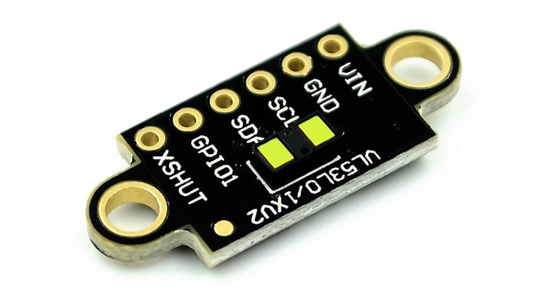
We chose these as distance sensors over the more common and cheaper ultrasonic sensors because of the higher data rate, and precision from a small beam angle. They were also consirably smaller, and advanced functions such as selecting the FOV.
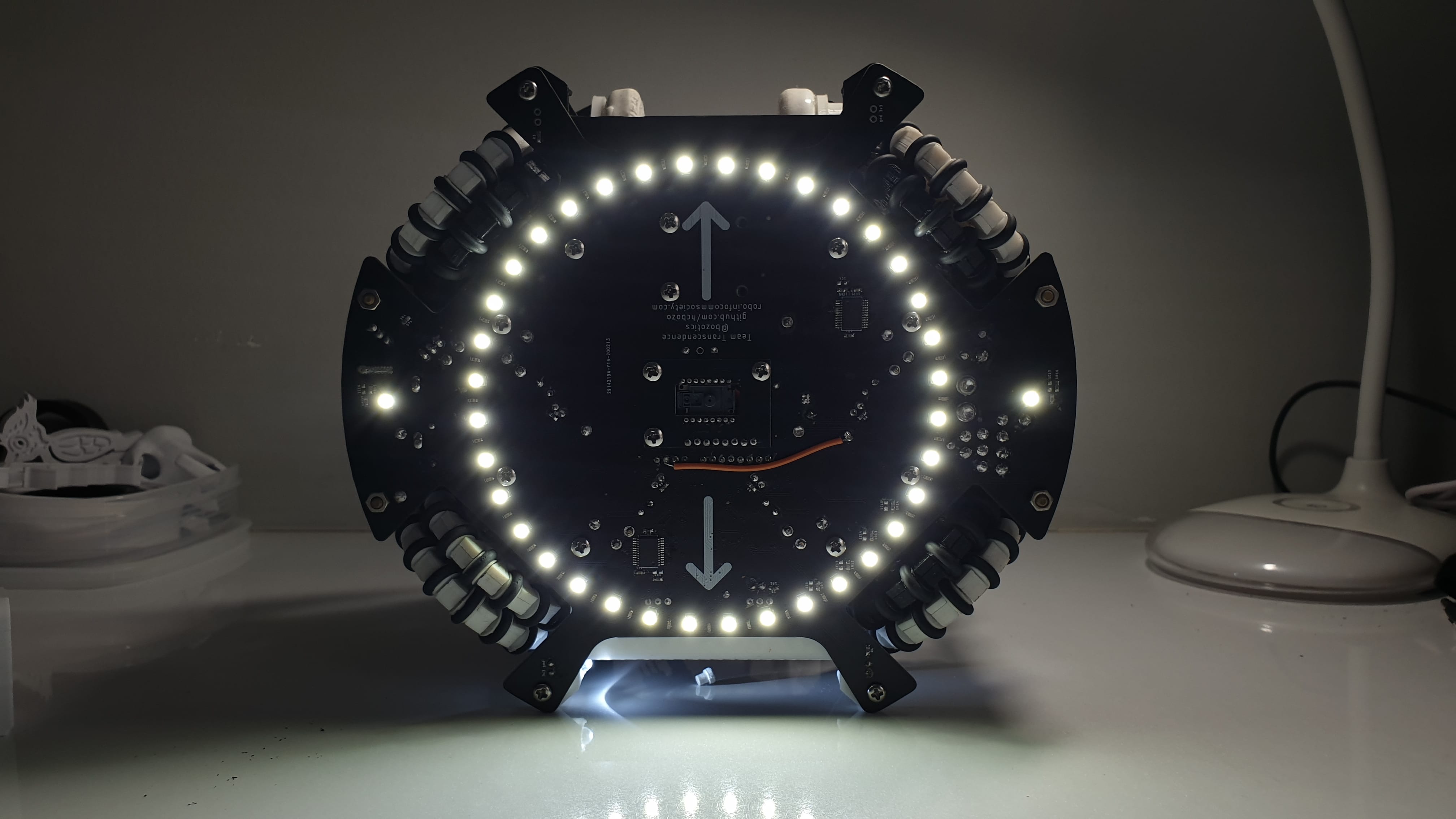
Light Sensor
We use 40 white 3528 LEDs and ALS-PT19 phototransistors for our bottom light sensor ring. These were multiplexed using 74HC4067 ICs.
We chose the ALS-PT19 because it was small (0603 package) and cheap. Previously, we have used TEMT6000 phototransistors, however they were annoying to solder, expensive and relatively large (1206 package).
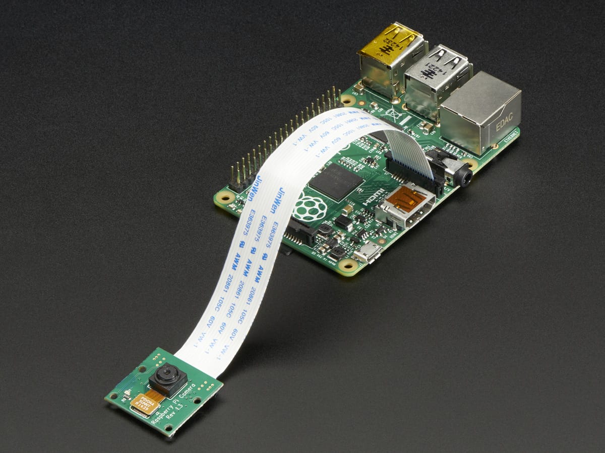
Camera
We use a RPi 3B(+) with a RPi Camera V1 for ball tracking and localisation due to its high processing power and flexibility.
Debugging
RGB LED Ring
We used 16 WS2812B individually addressable RGB LEDs (Neopixel) in a ring to aid in our debugging. These LEDs can highlight the direction of the ball, goals, robots, or any other debugging information without us needing to connect to serial terminals of the µCs or the RPi.
Bluetooth
We have a HC-05 bluetooth module for communication between robots as well as debugging via phones. This communication between robots allows for advanced strategies like attack / defence role switching, or to “extend” the FOV of the camera since both robots can be used to help the other localise or track the ball.
We also plan to eventually make an app for our phones to connect to the robot via bluetooth for debugging rather than downloading a new program with changed parameters every time we wanted to tune some parameters or read and debug sensor values