⚡ Electronics #2
Communication, interference,
and how everything fits together
Contents
- Analog communication
- Digital communication
- Definitions
- Communication protocols
- Interference
- Integrating everything
How do we “communicate”?
Senses:
- Vision
- Hearing
- Touch
- Balance
- Taste
- Smell
All of these are “analog”
What is “analog”?
From Wikipedia:
“Analog transmission is a method of conveying […] information using a signal which varies in amplitude, phase, or some other property”
Most “common sense” since it can vary
However, microcontrollers cannot do analog well
Bus capacitance, stray inductance and resistances, all affect the analog signal massively.
For the communication to be reliable,
we need it to be digital.
Terminology
Digital bytes
From Wikipedia:
The byte is a unit of digital information. It is the smallest addressable unit of memory in many computer architectures.
… and bits (binary digit)
From Wikipedia:
A bit is the smallest unit of storage. The modern de facto standard of eight bits in a byte permits binary values 0 through 28=255 for one byte. Modern architectures typically use 32- or 64-bit words, built of four or eight bytes.
What is a “digital” signal?

Duplex
once again from Wikipedia:
A duplex communication system is a point-to-point system composed of two or more connected parties or devices that can communicate with one another in both directions.
Half- and full-duplex

Asynchronous
Clock & Multiplexing
Basically a metronome for digital synchronous circuits.
| implementation | data rate | configuration | |
|---|---|---|---|
| synchronous | simpler | faster | easier |
| RX is controlled | no start bit | set 1 baud rate | |
| asynchronous | complex | slower | tougher |
| RX is unpredictable | need start bit | set 2 baud rates |
| multiplexing | interference | power use | |
|---|---|---|---|
| synchronous | easier | bad | more |
| RX is controlled | clock signal can be antenna | clock always on | |
| asynchronous | insane | better | less |
| RX is unpredictable | data only live when needed, no clock | no clock |
Differential Signals

Cyclic Redundancy Check (CRC)
Basically sum of the data and divide it
eg, if the data is 10001100, parity bit is 1:
Network topologies


Protocols
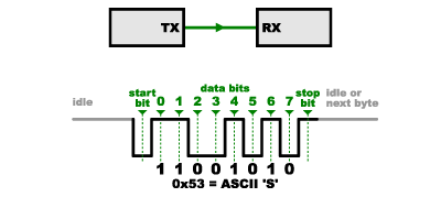
UART
- Asynchronous
- Full-duplex
- Preferred choice
TX 🡒 RX
RX 🡐 TX
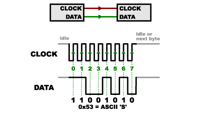
I2C
- Synchronous
- Half-duplex
- Prone to interference:
do not use over long wires - Made to use with “sensors”
Most sensors use this
SDA ⟺ SDA
SCL 🡒 SCL
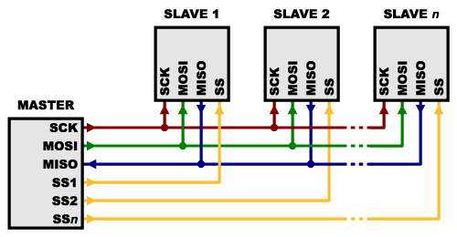
SPI
- Synchronous
- Pseudo Full-duplex
- Fastest, but “Bulkiest”: 4 lines
- Easy in hardware, complex in code
- Used mostly in display drivers
MOSI 🡒 MOSI
MISO 🡐 MISO
SCK 🡒 SCK
SS 🡒 SS
Miscellaneous
We don’t really need to know the next few for cup, they are mostly used for other industrial purposes
These are all differential protocols. They usually don’t exist for normal microcontrollers since it’s difficult to implement
USB (2.0)
- (A)synchronous
- Half-duplex (up till USB3)
- Differential
- Industry standard
- Very fast but complex
- Requires accurate clock
D+ ⟺ D+
D- ⟺ D-
CAN, RS485 / LVDS
- “all the others”
- Differential
- CAN is used in cars
- The others have industrial applications
- RS485 does not define a protocol
Probably no time to do interference separately, it’s boring anyways and it only really occurs for i2c so:
- i2c requires very very precise timing signals
- has some wonky pull up system since it is open drain (you pull it low but leave it open and don’t drive it high)
- together with a bidirectional data wire, it is very very prone to interference.
tl;dr, if you need to use i2c (most probably will):
- keep wire lengths short
- maybe don’t use the 400kHz fast mode (probably don’t need it to be that fast in reality anyways)
- ensure wires DON’T PASS BY MOTORS
- and try to keep buses separate for critical sensors (like BNO055!!!!!!!!!! VERY IMPORTANT!!!!!!)
wherever possible (mostly between µC) opt for UART as it’s more stable and the complex hardware implementation is done for us already.
SPI may be preferred but slave mode is not always well implemented in hardware, and software emulation is not that good
But we cannot escape i2c, and it’s not THAT bad anyways, mostly just BNO055’s implementation and wonky pull ups.
| I2C | SPI | UART | AIN | PWM | Others |
|---|---|---|---|---|---|
| TOF | Mouse | µC | Light | Motor | Ultra |
| Camera | Camera | RasPi | Neopixel | ||
| Color | OpenMV | OpenMV | Color | ||
| Compass | Display | ||||
| POT |

