⚡ Electronics #1
Transistors and some applications
Press s for speaker notes, backspace to delete random annotations
Contents: Transistors
Bipolar Junction Transistors
MOSFETs
Darlington Pair
IGBT
Contents: Applications
Low battery detection
Variable Resistor & Regulators
LDO
Buck Regulator
Boost Regulator
Motor Driver
Solenoid Switch
Transistors?
Moore’s Law in The Economist
What are transistors? May have seen it being thrown around before, here’s a
diagram from The Economist abt Moore’s Law
From Wikipedia :
“A transistor is a semiconductor device used to
amplify or
switch electronic signals and
electrical power.”
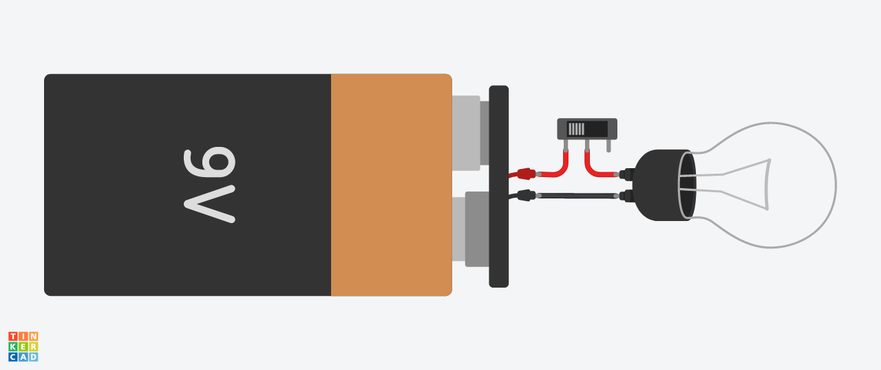
Normal way to switch a light bulb
Normally, when we want to turn on and off lightbulbs or other high powered
components, we use a switch.
However, what if we want to control these automatically?
Eg, in a Smart Home, when you reach home you want it to turn on automatically.
You will need a Microcontroller to do that…
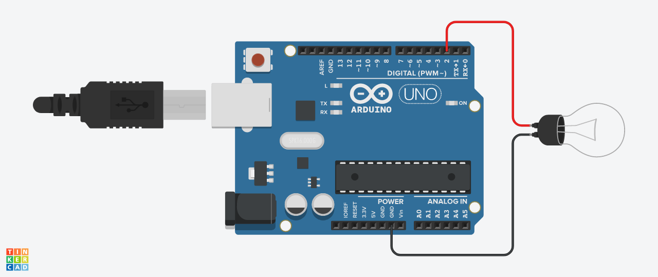
Arduino switching a light bulb?
Instinctively, we may think of this: using a microcontroller’s digital pin
(which you can program to output 1 or 0) to switch the bulb.
however…
From Arduino’s Tutorial :
“pins can source (provide positive
current) or sink (provide negative current) up to
40 mA (milliamps) of current to
other devices/circuits. […] attempting to run high current devices from
them, can damage or destroy the
output transistors in the pin, or damage the entire Atmega chip.”
The arduino only allows for 40mA MAX to be output from it’s pins. I wonder how
much amps a lightbulb requires…
Assuming Arduino runs at 5v,
W a t t s = V o l t a g e × A m p s Watts=Voltage\times Amps Wa tt s = V o lt a g e × A m p s 2.5 W = 5 V × A m p s 2.5W=5V\times Amps 2.5 W = 5 V × A m p s A m p s = 0.5 A > > > 0.04 A Amps=0.5A>>>0.04A A m p s = 0.5 A >>> 0.04 A
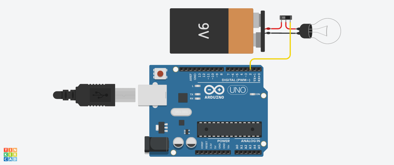
What if the Arduino could control the switch?
disclaimer: this circuit doesn't actually work
Electromechanical switch: Relay
One method is to use an electromechanical switch: a relay. A magnet would
control a metal piece to close or open the circuit. However, the “mechanical”
component is a major problem…
Problems
slow
prone to hardware failure
big
arcing
∴ A “digital” solution is required
Also, relays are commonly only used in AC circuits due to the zero-crossing
nature that will prevent arcing
There are many different types of transistors, but the first important one made
was thebipolar junction transistor (BJT)
NPN BJT
It is commonly used as an amplifier, eg. for
microphones and speakers
For switching a lightbulb, a BJT isn’t the most
suitable…
Those who study H3 semicon prolly know this, but I didn’t and that’s not the
point of this presentation anyways.
Draw current flow, explain beta amplification value, thus high voltage but low
current since saturation and beta can only be certain value
On PDF, go through saturation voltages and beta value, teach how to read
datasheet (the absolute max, recommended, graphs, what is important what isn’t)
switching is also relatively slow
Good video explaining BJT
good video explaining P and N doping silicon
metal–oxide–semiconductor field-effect transistor (MOSFET) is another type
of transistor, the gate is insulated from the rest of circuit thus there is low
input current and high input impedance
N-ch MOSFET
For a very high power lightbulb, power losses may
become severe…
Go through why it’s good: the high input impedance, so it is specifically made
to be a switch, can support high current
But input parasitic capacitance issues, so must put a resistor to smooth the
input current since constant charge
But but relatively high output impedance, means output power losses, breakdown
voltage relatively low
Explain graph, issues with Vgs , usually use a charge pump to get
voltage up
Good video explaining MOSFET
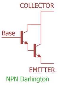
to solve the input issues of the MOSFET while acheiving the (relatively lower)
output impedance of a BJT, a darlington pair configuration can be used
darlington pair configuration
But Vce is doubled, so more power
losses
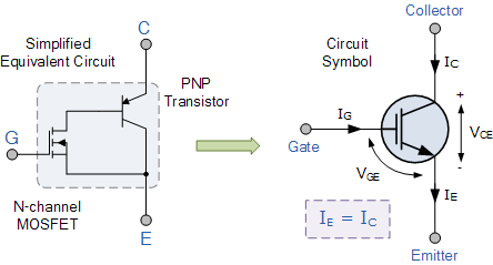
insulated gate bipolar transistor (IGBT) combines the low output impedance
of a BJT, high input impedance and high switching speed of a MOSFET to make a
very high powered transistor.
IGBT
But this is usually a lot more expensive and
large, for most cases it’s overkill
since we want low input impedance, we use mosfet as input to drive low output
impedance BJT. This is also a “PNPN” transistor.
But this is expensive and usually overkill, also very large in size
good writeup about this
For powering a lightbulb, a MOSFET is probably the most suitable
A lightbulb isn’t THAT high power to require a IGBT or Darlington pair
We are digitally controlling the lightbulb using a microcontroller, so we
don’t need analog amplification
Cost effective, small, easily available, commonly used
Going back to the original problem…
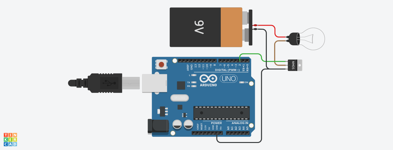
MOSFET LED Switch
Schematic Diagram
MOSFET LED Switch Schematic
Teach how to read schematic, common notations (net label, no 4 crossing,
junction)
Explain the pull down resistor, and the series resistor
Low Battery Indicator
NPN BJT Low Battery Indicator
Explain voltage divider, 0.6v saturation, show what saturation means (transistor
acts as zener), show on circuitJS
Variable Resistor
MOSFET as Variable Resistor
Explain MOSFET in linear region, so we can control resistance by on-off time,
hence explain PWM
Related AppNote
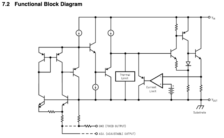
Low Dropout Regulator (LDO)
LM1117 LDO Block Diagram
Explain what is a block diagram, we don’t actually need to understand but
there’s a bunch of transistors around
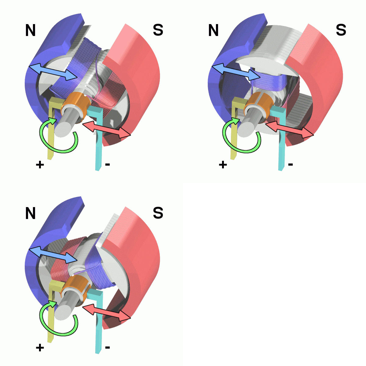
Brushed Motor
Brushed DC Motor GIF
briefly explain motor action, current cause B-field, reversing current cause
reversing B-field
show on tinkercad
don’t move on to next slide, show on chalkboard thinking behind full bridge, eg
we want to make current flow in the same direction at the horizontal part, from
alternate directions in the vertical part
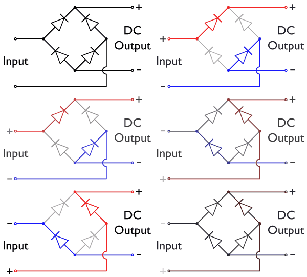
Full Bridge Rectifier
Full bridge rectifier GIF
show on chalkboard how to come up with a full bridge design, the thinking
process of how to convert AC to DC, then link to converting DC to AC
don’t move on to next slide, show on chalkboard how to convert that idea into
full bridge, eg we want to make current flow in alternate directions at
horizontal part, so current must come in from left/right side to change it from
the vertical DC part
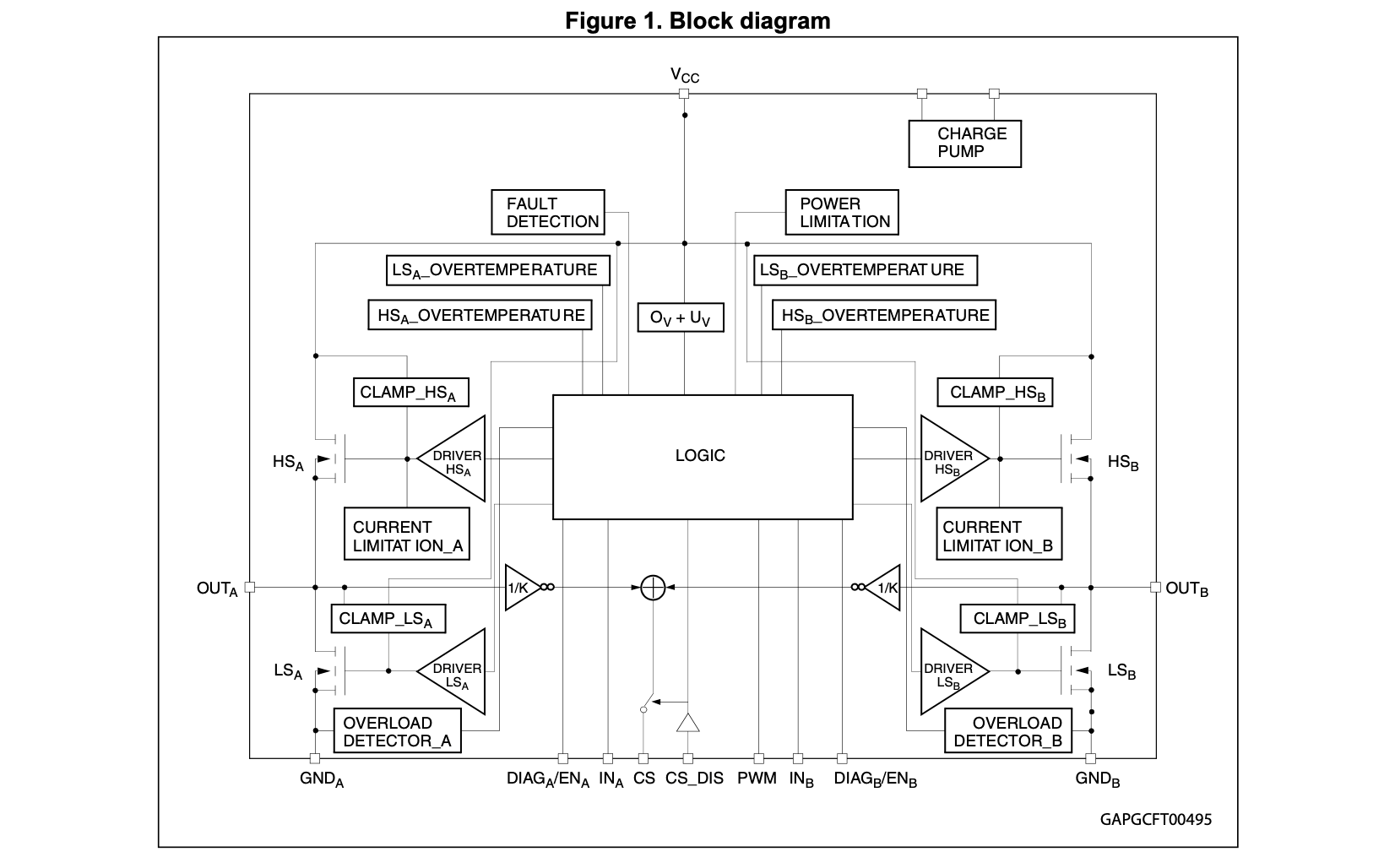
Motor Driver
Motor Driver Block Diagram
point out where the MOSFETs are, explain speed is controlled by PWM
emphasise that block diagrams aren’t actually that important whenever they’re
looking at datasheets, we use them here a lot just to explain how they are found
in the things we use
if have time go through the motor datasheet and key specs
Driving a linear solenoid
We usually run the solenoids at ~60V, ~2A. This results in huge spikes in current
and voltage we have to contain.
We first used a relay, but we experienced arcing due to this
large power draw and
inductive nature of the solenoid.
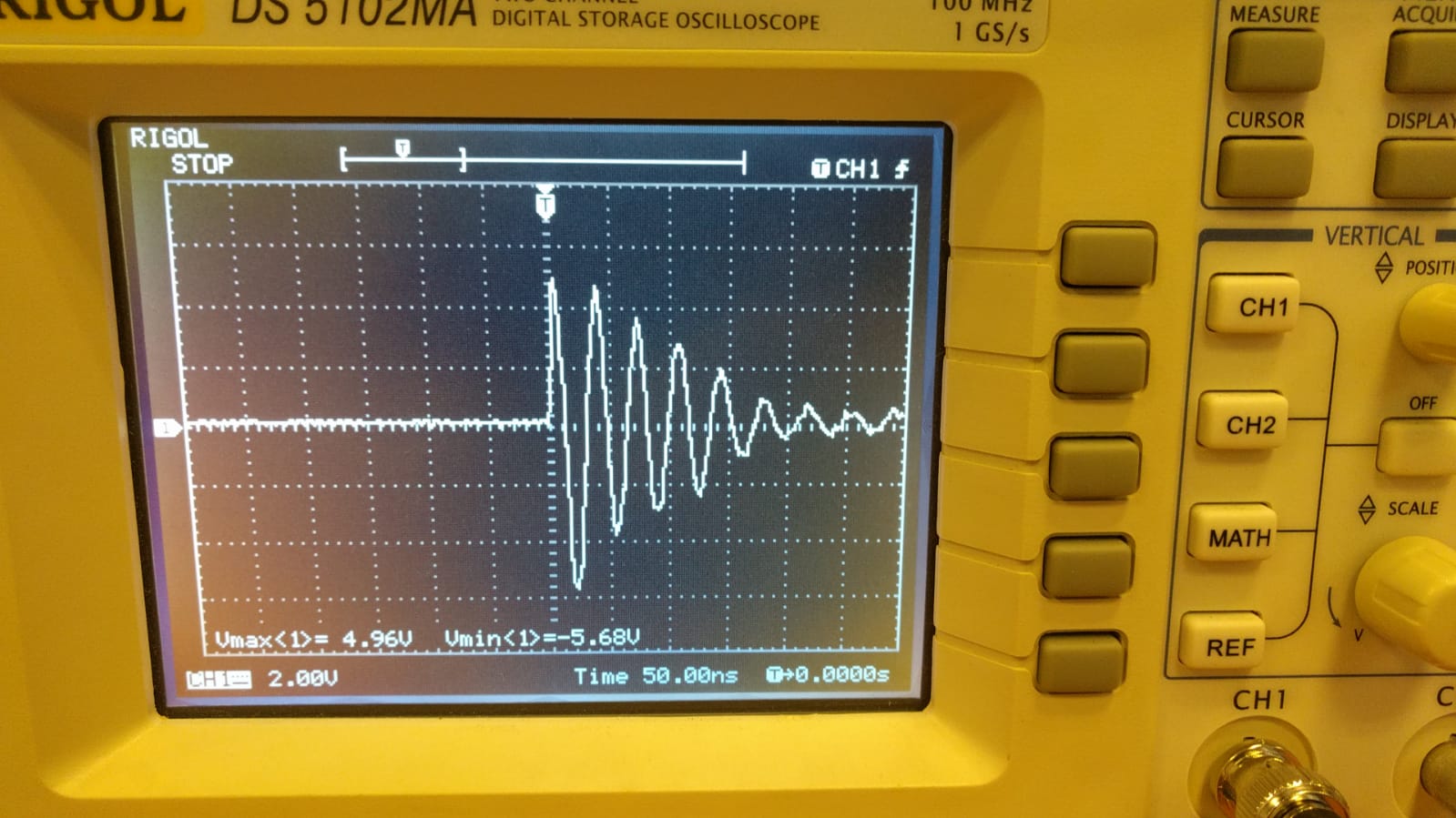
Current spikes
Oscilloscope reading of voltage across 0.4Ω resistor
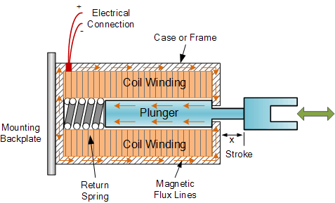
Solenoid’s inductive nature
Linear solenoid cross section
Explain what is an inductor, basically a coil, so coil stores magnetic energy.
When power is removed, this magnetic energy is still there, it doesn’t get
removed as well. Now this energy has nowhere to go, thus the voltage will just
keep increasing and building up until MOSFET diode reaches breakdown voltage
MOSFET switch
Using a MOSFET to switch a solenoid…?
Explain what is an inductor, basically a coil, so coil stores magnetic energy.
When power is removed, this magnetic energy is still there, it doesn’t get
removed as well. Now this energy has nowhere to go, thus the voltage will just
keep increasing and building up until MOSFET diode reaches breakdown voltage
Flyback diode
Adding flyback diode to contain inductive ‘kickback’
Zener diode
Adding zener diode to dissipate energy
Explain what is a zener diode, maintains a voltage difference across. This
allows it to dissipate more energy during the OFF state, which helps save the
MOSFET. Not really needed or used online, just a safety addition
MOSFET Vgs Threshold Issues
‘CONTROL ’ voltage of 3.3v to drive MOSFET?
show 2n7000 MOSFET datasheet graph of Vgs , so MOSFET will get hot due
to Rds power losses
Using 12v battery as gate drive
Using 12v for gate drive
Explain how smaller MOSFET has smaller breakdown voltage so can’t use it alone,
but bigger MOSFET needs higher Vgs to acheive lower Rds ,
thus you use both together
Explain how gate drive isn’t based on “absolute voltage”, but is based on
Vgs , means it’s relative to the source voltage, that’s how this
circuit works
