Localisation
We have came up with a method for finding the position and orientation of the robot using purely the camera, which we also use to be able to face “straight” forward.
Camera
There are usually two big issues when it comes to camera localisation:
- Inaccuracy: Due to noise from the camera’s image, the areas detected as objects are constantly changing, which would change the distance measurements (from our testing, the angle remains quite stable). Besides, the further away an object is, the more stretching (distortion) would occur to its image on the mirror. Hence, any small fluctuations in the object’s position could cause large distance changes on the image.
- Lack of reliabilty: The field is often crowded with many robots which would severely limit the robot’s field of view. This prevents the robot from being able to constantly see the landmarks it needs to calculate its position.
However, our method has proven to be rather successful in circumventing these problems. Note that our “localisation” algorithm finds the vector from the robot to a specific point on the field, not necessarily finding out the current position of the robot (since localisation is, more often than not, simply used to find out where to move to reach a desired destination).
Position
At first glance, it might seem logical to simply form the vectors from the robot to the 2 goals, and since we know the real-life positions of the 2 goals relative to each other, it would thus be possible to triangulate the robot’s position relative to the 2 goals. However, due to the inaccurate distance measurements as stated in point 1 above, this would not yield good results, since it relies on the camera measurements matching up to the real distance of the goals.
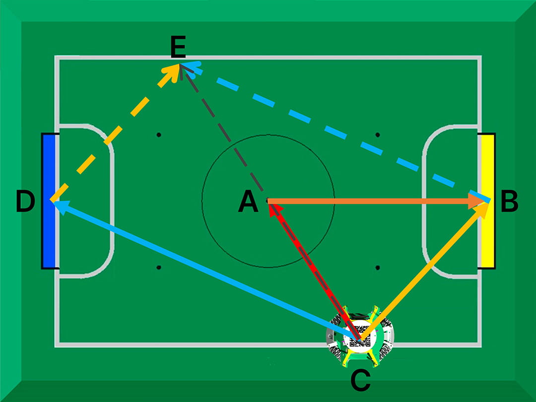
Hence, our method avoids absolute distances completely by first finding the relative centre between the 2 goals. In the diagram below, we see that given yellow vector CB and blue vector CD, their vector sum adds up to CE, for which halving its magnitude would create vector CA that points directly to the centre point. The benefit of finding the centre point first is that it’s a relative reference point i.e. positions on the field will be based on this reference point, but its a relative point between the 2 goals rather than a “fixed” point based on knowledge of absolute distances.
Once we know the centre point, we can find vector AB = CB - CA. Vector AB is very important as this represents the vector that tells us the direction of where the front of the field is (assuming facing the yellow goal is the “front” position).
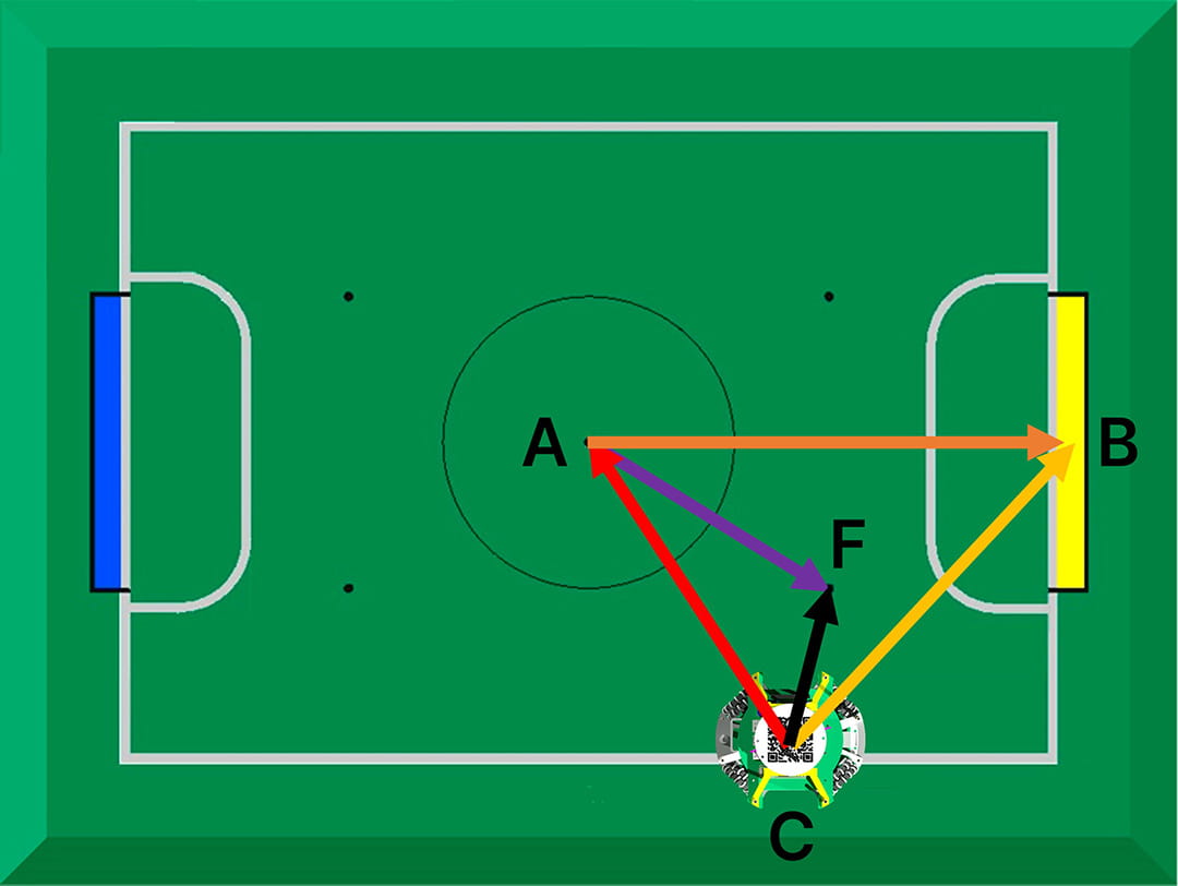
Now, let’s say we want to move to point F. We already know the angle of vector AF relative to vector AB, since angles are quite accurate and “real-life” values can be used. For the magnitude of AF, we know the real-life ratio of its length relative to the distance between the 2 goals. Using this ratio, we multiply it by the total goal distance BD, to give us the relative length of AF! And just like that, the vector from the robot to the point is simply CF = CA + AF!
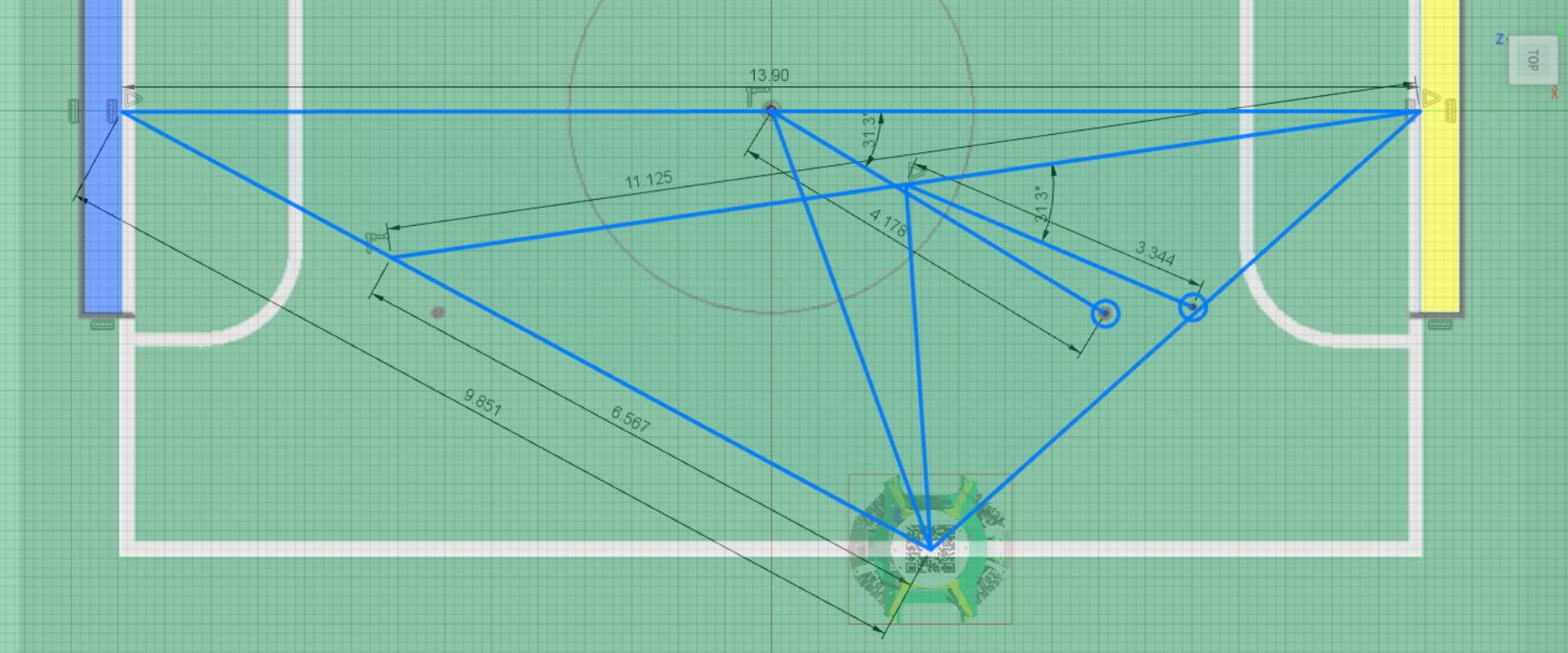
To show that this method is resilient to “false” distance measurements, the diagram below shows a scenario where the robot detects the correct blue goal angle, but its distance is detected at around 2/3 of the actual distance (note that in reality, our maximum deviation is only around 75% of the actual distance when the robot is furthest away from the goal).
The diagram is drawn to scale (in Fusion 360) and the first circle to the left, shows the real position of point F, while the circle more to the right shows the calculated position of point F. Even with a theoretical 33% measurement error, the final calculated position is only slightly deviated away from the real position, nowhere near significant to negatively affect the robot’s performance.
Orientation
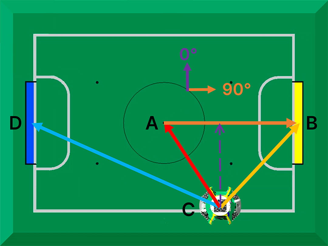
In order to find out our orientation, we simply take reference to vector AB. Since the information regarding landmarks are all in polar form (angle and distance), we work with all our vectors in polar form as well. Hence, the angle of vector AB is simply the current orientation of the robot. By applying an angular velocity that is proportional to the angle of vector AB, the robot can be made to face straight forward.
To orientate towards the blue goal as the “front” instead, we can just reference to vector AD instead.
Other Landmarks
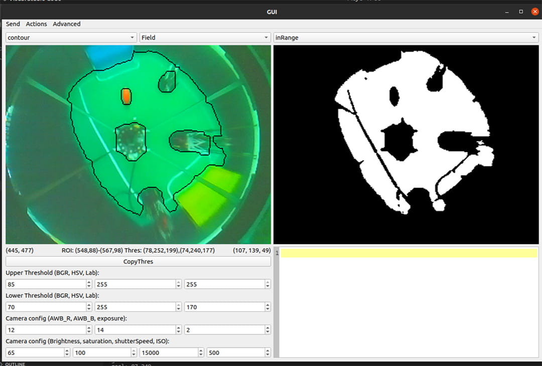
To further improve this, we can use the entire field instead. We are currently able to detect the entire field by tracking all that is green and drawing a “best-fit rectangle” around it. Simply looking at the angle of this rectangle relative to the front of the robot can easily tell us our heading. We did not have enough time to fully look into the feasibility of this, but it is definitely something we will try in the near future.
Light Sensor
While the line is not the most useful landmark on the field, it is the most trustable landmark since its detected by the light sensors which have virtually no chance of being interfered with.
When the desired point to travel to lies on a line, the robot not only travels in the vector to that point, but also does line tracking based on that vector, to reach the point with greater accuracy.
In addition, for edge cases where the robot is on a line and is unable to use any of the camera’s landmarks for orientation, it can simply orientate itself to be parallel with the line in order to face straight forward.
TOF
Coming eventually, maybe never, definitely not soon, but probably maybe…