Mirror Design
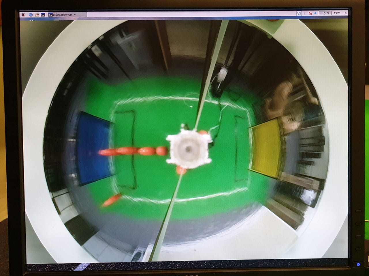
In order to view the whole field with only one camera, a curved mirror is used to provide 360 degree vision for the robot i.e. catoptric system.
Theory
Background information
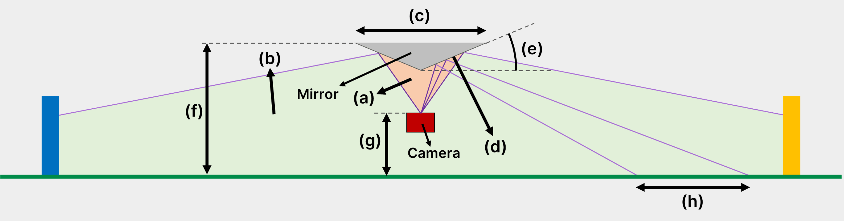
| No. | Term | Definition |
|---|---|---|
| (a) | Camera FOV | (Red area) Maximum angle range that the camera is capable of seeing |
| (b) | System FOV | (Green area) Maximum angle range that the entire catoptric system is able to see |
| (c) | Mirror diameter | The diameter of the mirror at the top (largest diameter) |
| (d) | Mirror profile | Refers to the shape of the half section of the mirror |
| (e) | Mirror angle | The angle of elevation of the mirror profile relative to the ground, at a specific point |
| (f) | Mirror height | Distance from the top of the mirror to the ground |
| (g) | Camera height | Distance from the camera sensor to the ground |
| (h) | Field distance | The distance on the field represented by a certain camera FOV angle range |
Note: In reality, light rays reflect off of objects into the camera, but for ease of understanding, all ray diagrams and explanations should be interpreted from what the camera sees, so the “rays” are perceived as moving from the camera to the field.
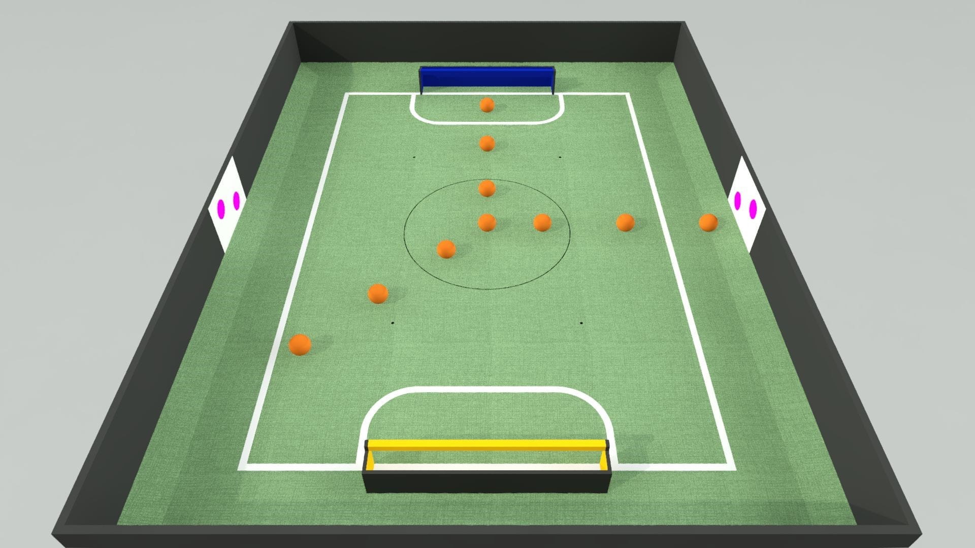
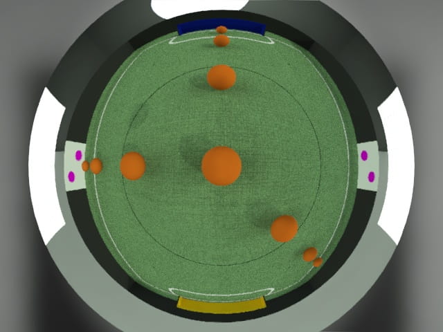
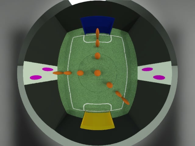
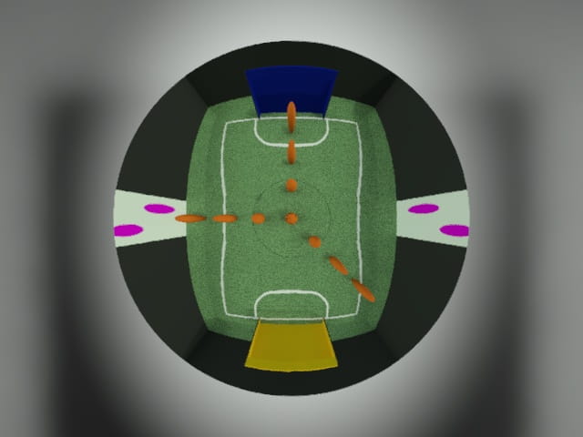
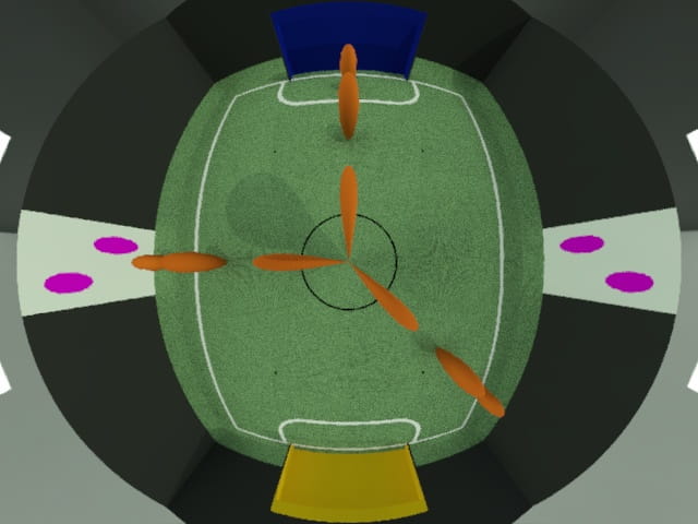
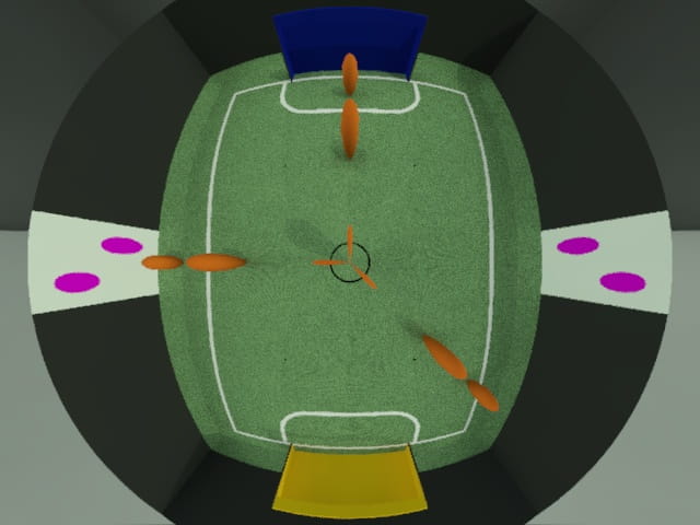
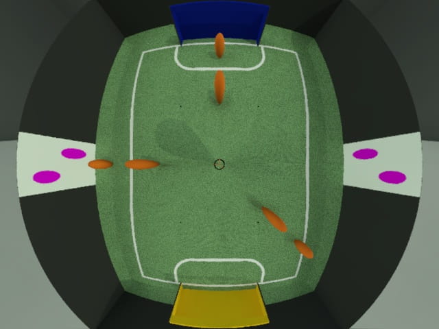
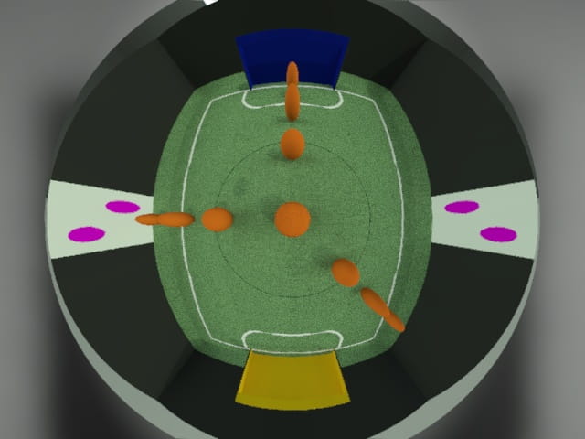
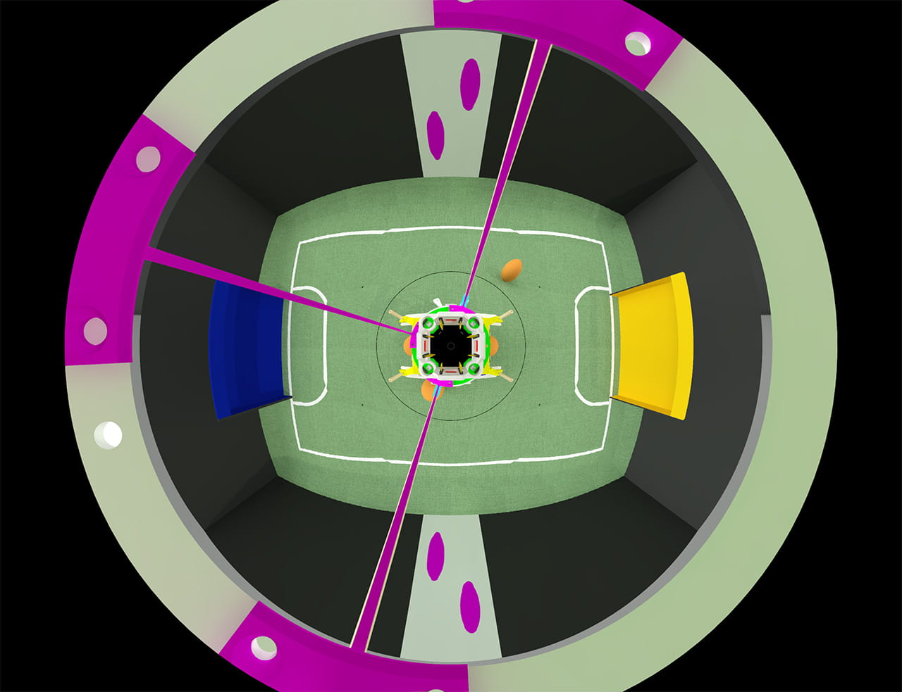
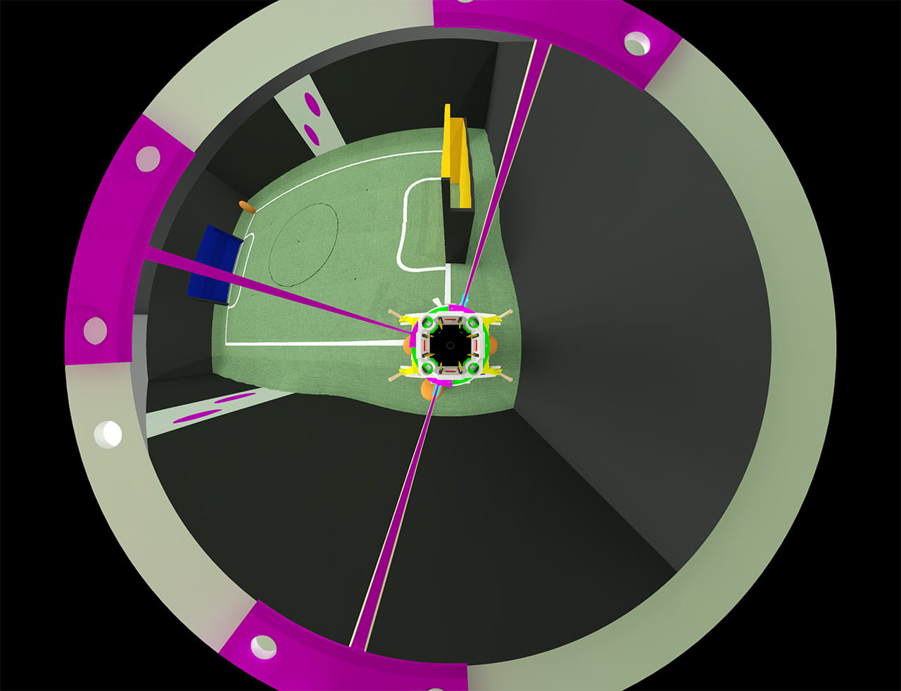
For all mirror renders in this section, the actual field setup is as depicted below. The first ball in each row of balls are 200 mm away from the centre, and the following balls are 300 mm from the ball in front of it. The camera and mirror is aligned at the centre of the field and all images are rendered at 640 by 480 px, the actual resolution our Raspberry Pi camera is running at.
Before jumping into the design, we set a few basic requirements for our mirror.
Requirement 1: System FOV must be large enough to cover the whole field at all times, regardless of position and robot orientation
Requirement 2: Mirror must be able to show goals and balls as clearly as possible by producing a minmially distorted image
Requirement 3: System FOV should be kept within the field to minimise wasted pixels in the image looking outside of the field.
To work towards these requirements, we found that there are 3 main parameters in tweaking our catoptric system.
Mirror curvature
As the angle of elevation of the mirror profile increases, given the same ray, the angle of incidence on the mirror surface increases too. By law of reflection (angle of incidence = angle of reflection), the FOV of the system will increase, assuming the mirror diameter remains constant (covers constant amount of camera’s FOV).
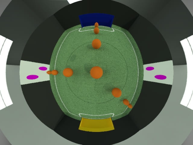
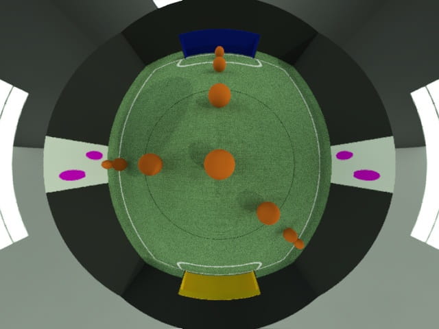
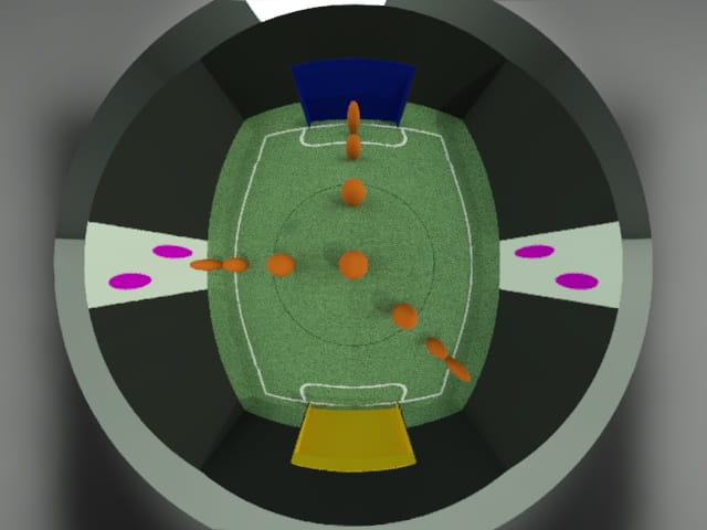
Although increasing the system’s FOV might sound like a good thing, logically speaking, more “information” is cramped into the same image size, so the objects have to become more compressed, which makes them smaller and more distorted. The renders below are of conic mirrors with a difference in angle of elevation of 5 degrees. It is clear that whilst the higher angled mirror has a larger FOV, the objects in the image are much more distorted.


In addition, practically speaking, most of the camera modules we use have a relatively large aperture size (Raspberry Pi Camera V1 has a focal ratio of 2.9), and thus a shallow depth of field. Hence, a mirror with a steep angle may end up having some parts being out of focus.
Constraint 1: Mirror angle should be minimised.
The rate of change of the angle of the mirror profile per unit distance from the centre (the gradient) is what gives the mirror its unique shape. If the rate of change is a constant, the mirror profile will be a line, forming a conic mirror. If the rate of change is increasing, the mirror profile will be some curve function, often a parabola, forming a parabolic mirror. The characteristics of a conic and parabolic mirror complement each other.
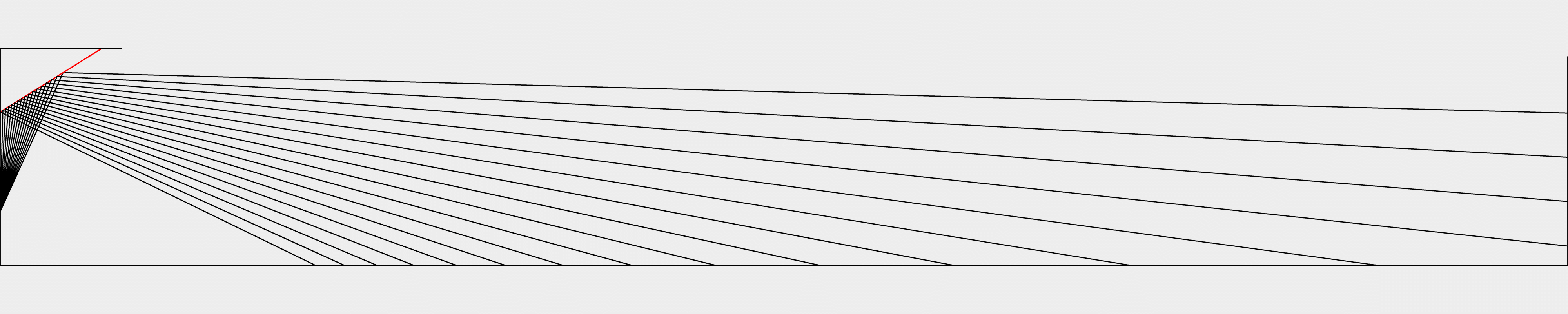
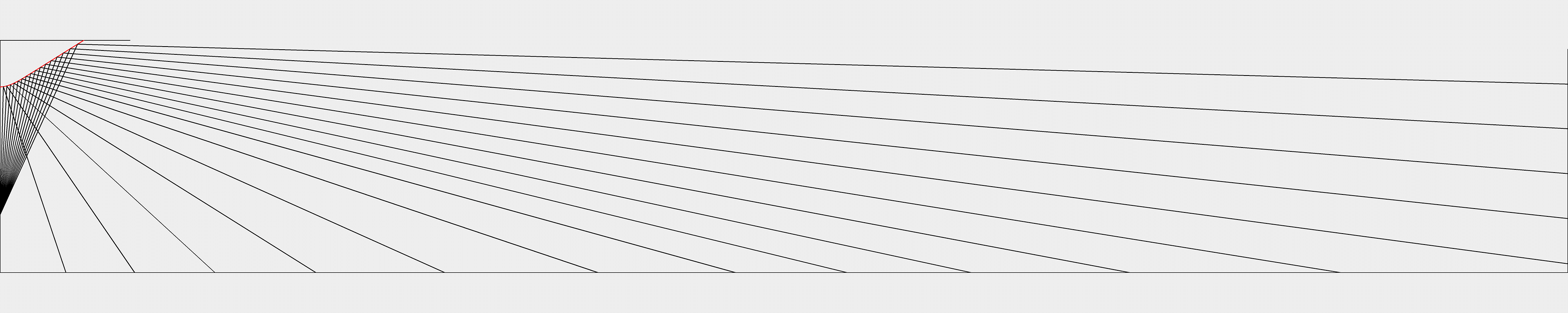
With a conic mirror, as you move closer to the centre, the angle of incidence decreases. Since the angle of reflection is the same as the angle of incidence, for a unit n decrease in the angle of incidence, there is a 2n decrease in the total deflection angle. Hence, the closer you get to the centre of the mirror, the same angle range represents a smaller distance on the field. This is why the closer the object is to the robot, the more stretched it gets.
Since the conic mirror has a fixed angle that is non-zero, it will always have a blind spot which is the region between the angle of reflections drawn when the camera ray angle is at 0 degrees.
With a parabolic mirror, as you move further from the centre, the angle of incidence increases exponentially. Similar to the logic of the conic mirror, given the same angle range, as the distance from the centre increases, the distance that angle represents on the field increases exponentially. Thus, the further the object is from the robot, the greater the compression effect is in the image.
While the field distance of a parabola does approach 0 towards the centre, the angle of the mirror also reaches 0 at the centre. This is why the parabolic mirror has no blind spots.
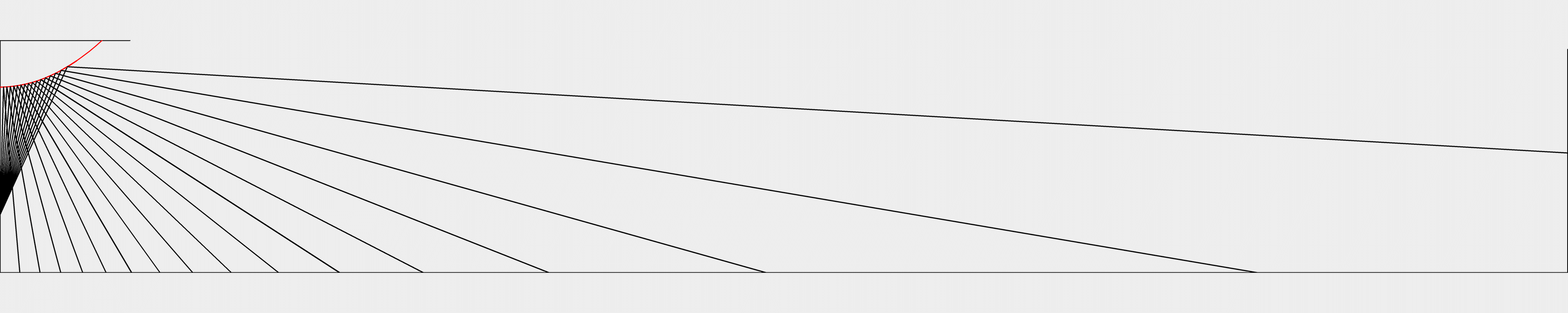
Comparing the 2 ray diagrams, it is quite obvious that the areas where the rays become more or less dense are exact opposites. Therefore, the ideal mirror shape should be a mix between a conic and parabolic mirror. For objects further from the robot, a conic mirror helps prevent compression of the objects in the image that would be present with a parabolic mirror, while for objects nearer to the robot, a parabolic shape removes the blind spot of the conic mirror and minimises the stretching effects of the image. This “cone-and-curve” shape is basically a hyperbola.
Constraint 2: Mirror profile should be a hyperbolic shape (“cone-and-curve”).
Mirror-Camera Distance
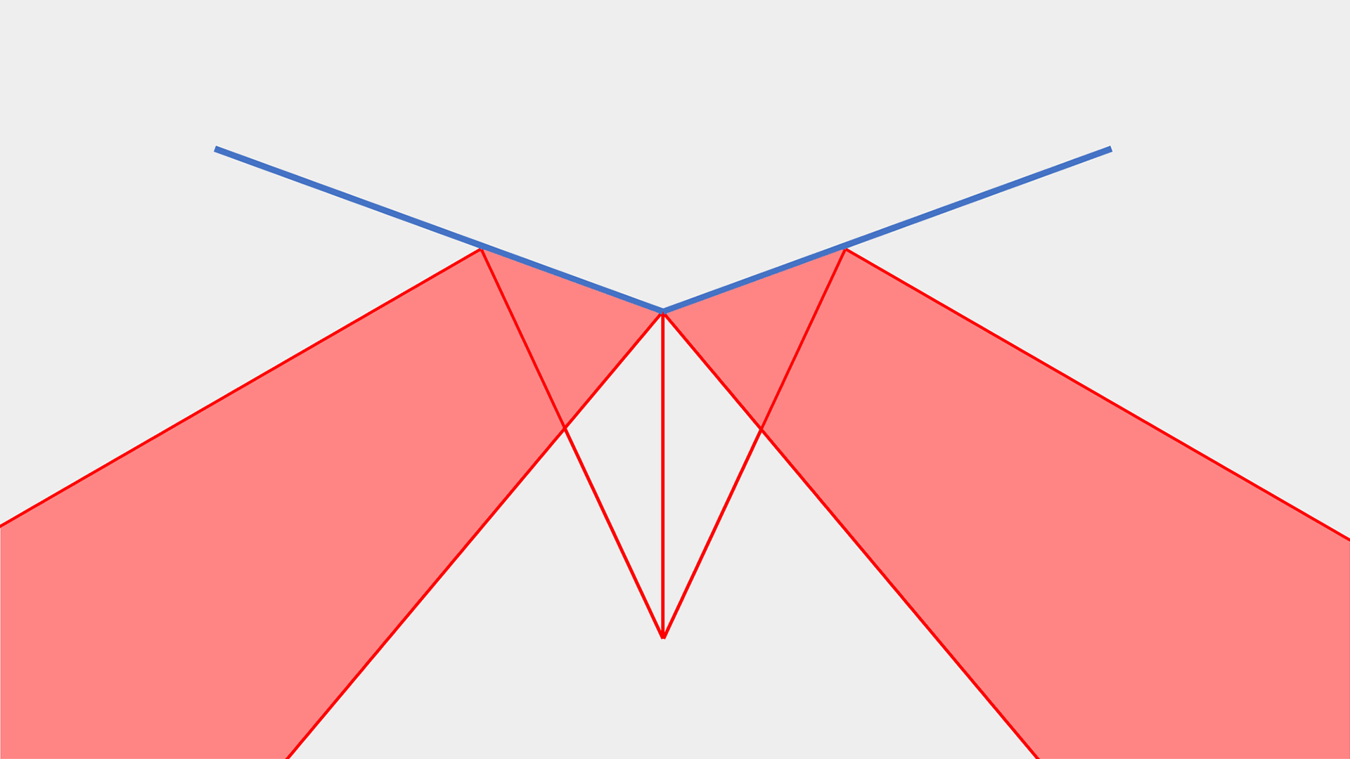
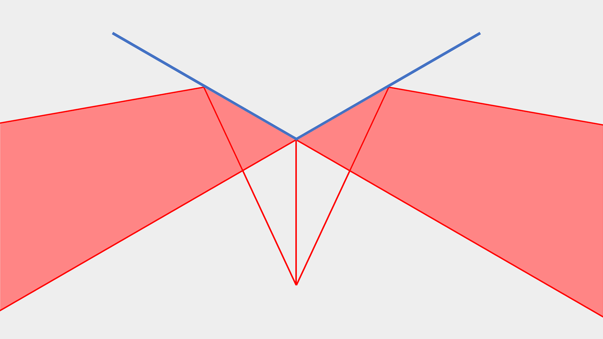
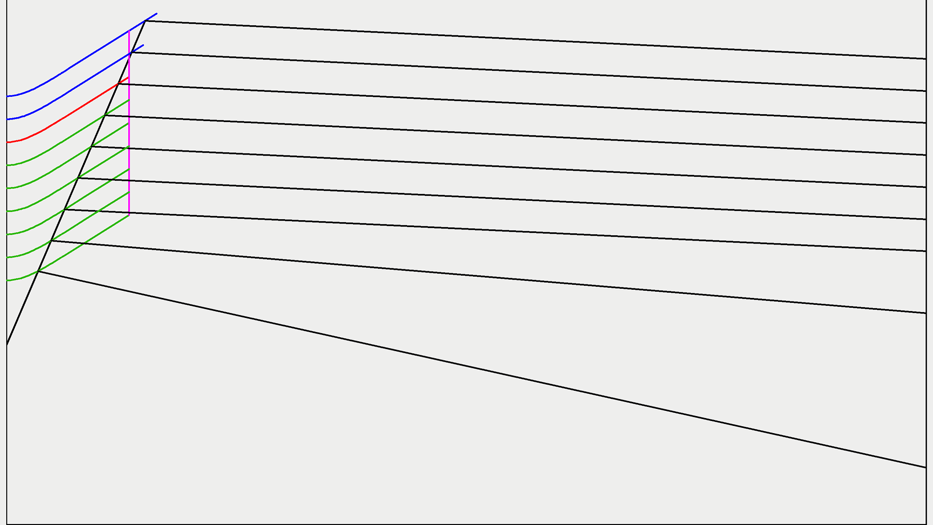
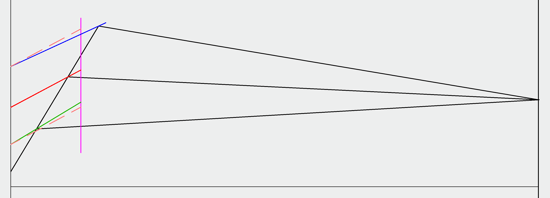
The larger the distance between the mirror and camera, assuming the camera’s height and mirror shape stays constant, the larger the FOV of the system, as long as the mirror diameter is increased to keep the area covering the FOV of the camera constant. In the diagram below, the ray represents the maximum FOV of the camera. If the blue mirror profiles were not extended from the original red profile, the system FOV would actually shrink because the max camera FOV is not fully covered by the mirror.
Here are the renders of the hyperbolic mirror at 3 different heights, 20 mm apart. This first 3 mirrors were not extrapolated to fully cover the camera FOV and it resulted in the system FOV becoming smaller as the mirror-camera distance increased.
This next 3 mirrors were extrapolated, which caused the system FOV to become bigger.
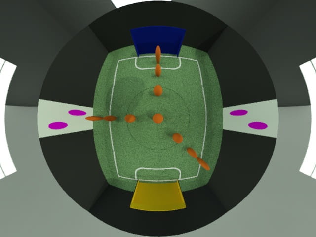
Note that the higher the mirror, the less effect the curved part of the mirror had on the image, since the angle range of the camera’s FOV that it covers decreases with increasing height. Also, notice how changing the mirror-camera distance alone doesn’t actually have a significant effect on the system’s FOV.
However, this can have a significant effect if thinking this way: Given an increase in the mirror-camera distance while keeping the area of the FOV of the camera covered by the mirror constant, to keep the same FOV of the system, the mirror angle can be reduced. The diagram below shows how with a fixed maximum system FOV and varying height, the mirror angle can become smaller the higher it gets (a conic mirror is used since it has a constant mirror angle).
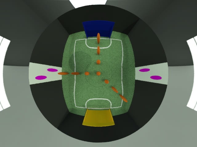
The following renders (from left to right) depict 3 mirrors with increasing distance from the camera (40 mm increments) and with decreasing mirror angles, that all produce a maximum system FOV which is roughly the same. Other than the blind spot in the middle, it is clear that as the mirror height increases and the mirror angle decreases to keep the maximum FOV constant, the distortion in the overall image decreases.
Constraint 3: Mirror-Camera distance should be maximised.
Catoptric System Height
The larger the distance between the catoptric system and the ground, asssuming the mirror-camera distance remains constant, the larger the FOV of the system. This is quite intuitive, since the higher the catoptric system is from the ground, the further the rays can travel and thus the system FOV increases.
Constraint 4: The catoptric system height should be maximised.
Ideal Mirror
It is evident that the last 2 factors, mirror-camera distance and system height, play a smaller role than the mirror’s curvature. This is because the field is extremely large compared to the robot and the last 2 factors are limited in their variablity to change the image since they are displacement-based changes and there is a size limit. On the other hand, mirror curvature influences angles of light rays, and any small change in angles at the mirror surface will become a large change in distance on the field due to its large size.
Summarising the ideal mirror based on the 4 constraints above, the mirror should be hyperbolic to produce the best image, the distance between the mirror and camera should be maximised so that the mirror angle can be minimised for least distortion, the whole system should be placed as high as possible, all while ensuring the system’s FOV is just enough to see the whole field, no more no less.
Designing
Many teams have used an array of mathematical approaches to determine the optimal equation for the mirror’s curve. We also tried doing so, referring to this paper which included a MATLAB program which supposedly derives a mirror equation numerically given a set of parameters. However, we were unable to get the code to work and we felt that this was just an overly complicated way of doing things.
Hence, we came up with our own intuitive, extremely simple, trial and error method with absolutely no math needed. *insert engineer vs mathematician joke here*
DIAGRAMS + COMPARED RENDER
MAKE VIDEO
Manufacturing
As much as designing the mirror is important, a mirror has to be manufactured properly in order to correctly translate the simulated performance into real life. Based on our research, we found 4 possible ways to make a mirror.
Gluing mirror sheets
A 2D net of the mirror shape is wrapped around a model of the mirror shape (usually 3D printed) and glued into place. This is arguably the simplest method to make a mirror. However, only a conic mirror can be made, and the line(s) where the ends of the net meets will be highly distorted.
This is mainly seen in a few lightweight teams e.g. M&A in RoboCup 2019 (Website), since the mirror needs to see the goals only, which are usually far away, and thus, the problems of a conic mirror is not an issue. Hence, this method was not suitable for us.
Moulding mirror sheet
A mould of the mirror shape is first created, usually with 3D printing. Next, a mirror sheet, typically made from PVC (Example), is heated up to a high enough temperature (around 300°C) that allows it to be pressed and moulded on to the mirror mould.
This is the most common mirror making method in most RoboCup teams. This can be done purely by hand, or with a vacuum forming machine for even greater accuracy.
INSERT MOULDING VIDEOS?? AND PICS
However, our experience with moulding mirror sheets for the past 2 years had been very unsuccessful. When moulding a parabolic mirror, the result was relatively good, but when moulding the hyperbolic mirror, the “conic” part of the mirror was really bad and it had many weird rings and artefacts that made the image terribly distorted. We suspect this is because along the straight sides, the mirror sheet will be unable to stretch fully to completely take on the straight edge. Also, since our mould is 3D printed, the mirror sheet cannot be heated to a higher temperature, nor can the mirror mould be preheated for easier moulding. Finally, the moulded mirror has to be cut out by hand and put in place by estimation, making it usually off-centred or slightly tilted.
Machining with Plating
A mirror model is machined from a lathe, followed by plating with some material to create a mirror finish. Some common examples are chromium electroplating and electroless nickel-phosphorous plating. This is more commonly seen in RoboCup MSL.
We did not opt for this method because we did not have much access to the chemicals and machines needed for these processes, and we had little knowledge about the plating processes to begin with.
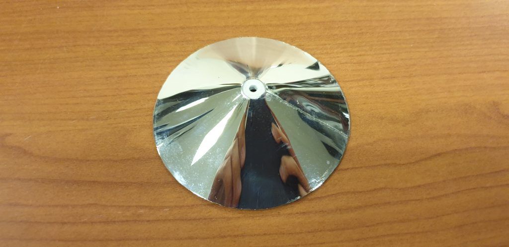
Machining with Polishing
A mirror model is machined from a lathe again, but to achieve a mirror finish, it is sanded and polished with progressively higher grits instead. This method has been seen in a few RoboCupJunior teams such as InfraReady (Drive folder), whom was our biggest inspiration into doing this.
We had thought about machining a mirror directly for a long time already, but we always thought it would be impossible to polish a metal to the point of a mirror finish (based on the limited YouTube videos on this topic). In addition, when asking machining services about the cost of achieving a mirror finish, they quoted the cost of making a mirror to be a staggering 100 SGD, which was why we laid off this method for the past 2 years. However, after seeing the well-documented process of machining and polishing mirror courtesy of InfraReady, we decided to try this out ourselves.
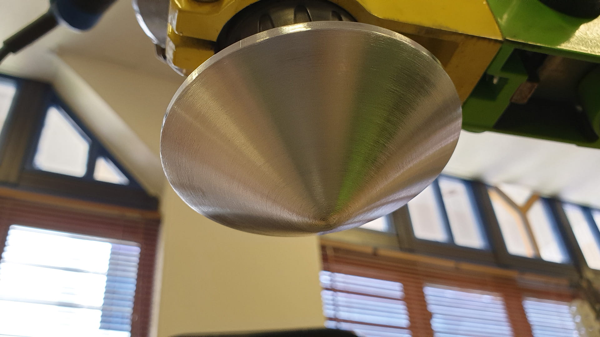
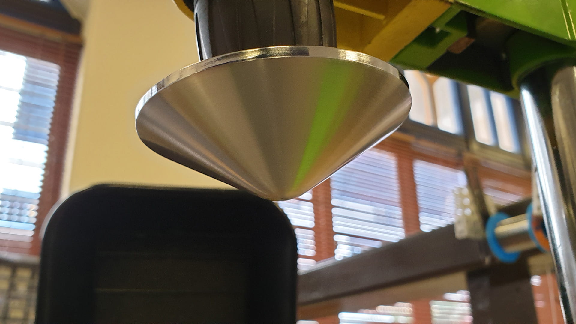
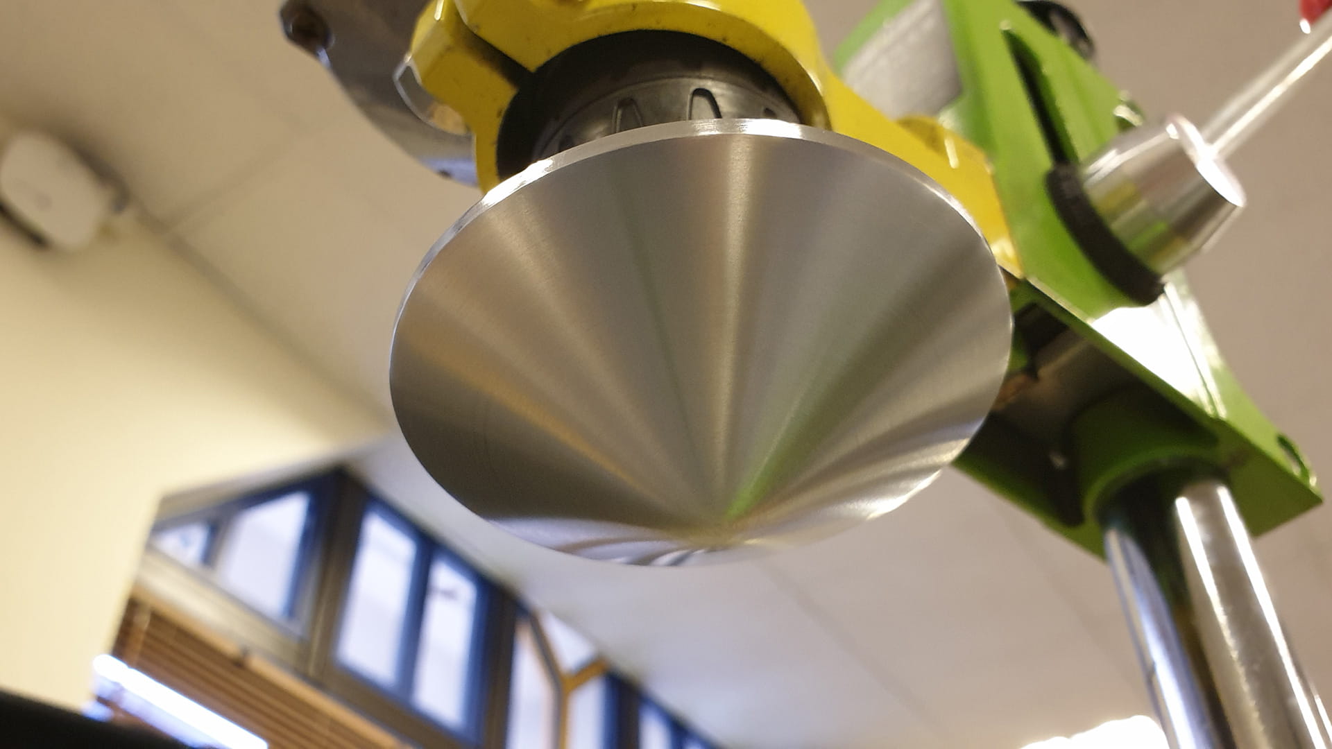
We acquired a Chinese manufacturer to create the mirror out of aluminium and a CNC lathe, and it only cost around 11 SGD per piece.
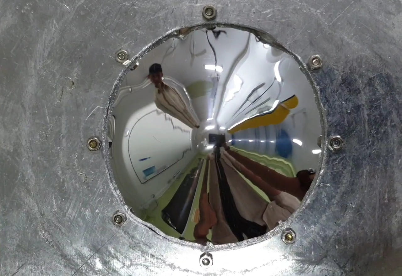
Following that, we attached the machined mirror to a high-powered drill, which functioned as a lathe. We sanded the mirror with progressively higher grit sandpaper, in the order of 100, 200, 500, 1000 and 2000. This was followed up with using Autosol metal polish and then finally with Meguair’s Nxt Generation All Metal Polysh, which was a less abrasive metal polish.
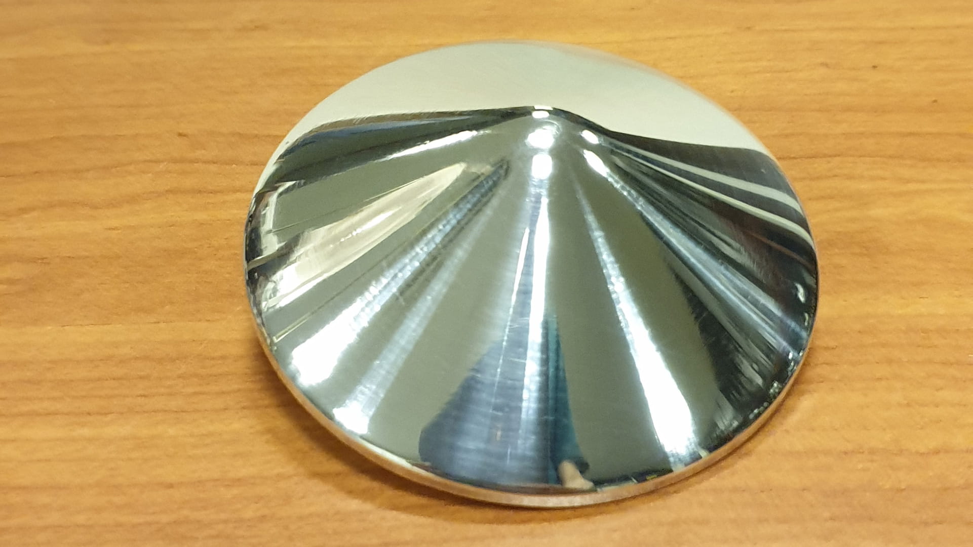
After this first time of polishing, the result was much better than we expected — it was definitely better than the moulded mirrors we had made in the past. However, after some examination, we realised that there were still many small scratches along the mirror surface.
Thus, we re-did the sanding process but with wet sanding, in true “bozotic” fashion. Using a plastic bottle as a water sprayer, we went onto our lab’s rooftop (due to constraints in draining and power plugs) we started from 500 grit sandpaper and worked our way up to 2000 again before using the 2 metal polishers. This helped improve the image slightly. Although scratches were still visible under examination, the image was already more than acceptable. Our Instagram post below goes through this process in detail.
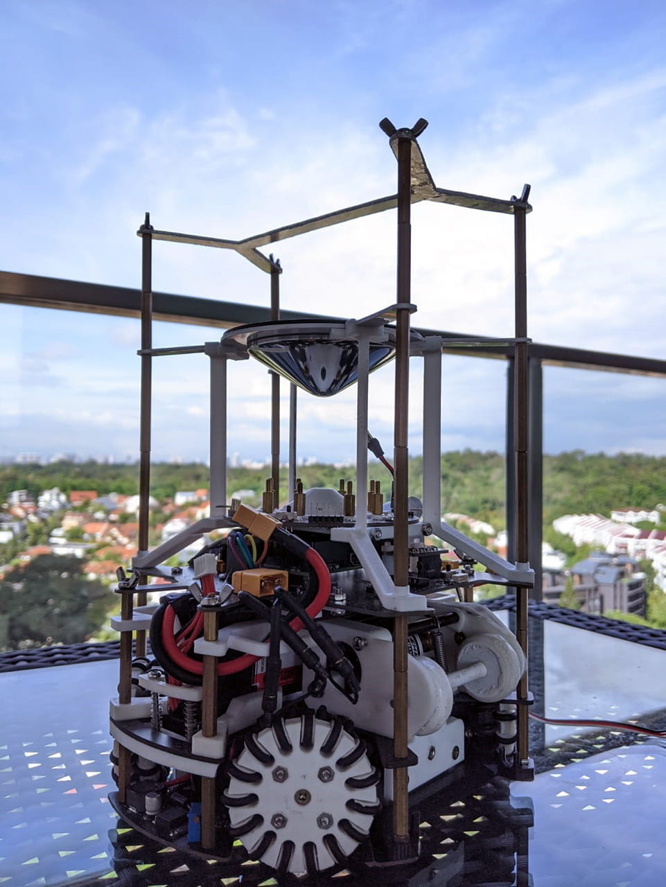
However, the mirror sees over the field, which means it is not the most efficient mirror shape. We had done this intentionally just in case the manufactured mirror produced different images from the rendered ones and it was better for the mirror to see more than less. More thoughts on what to improve about our mirror can be found on the AFI page.
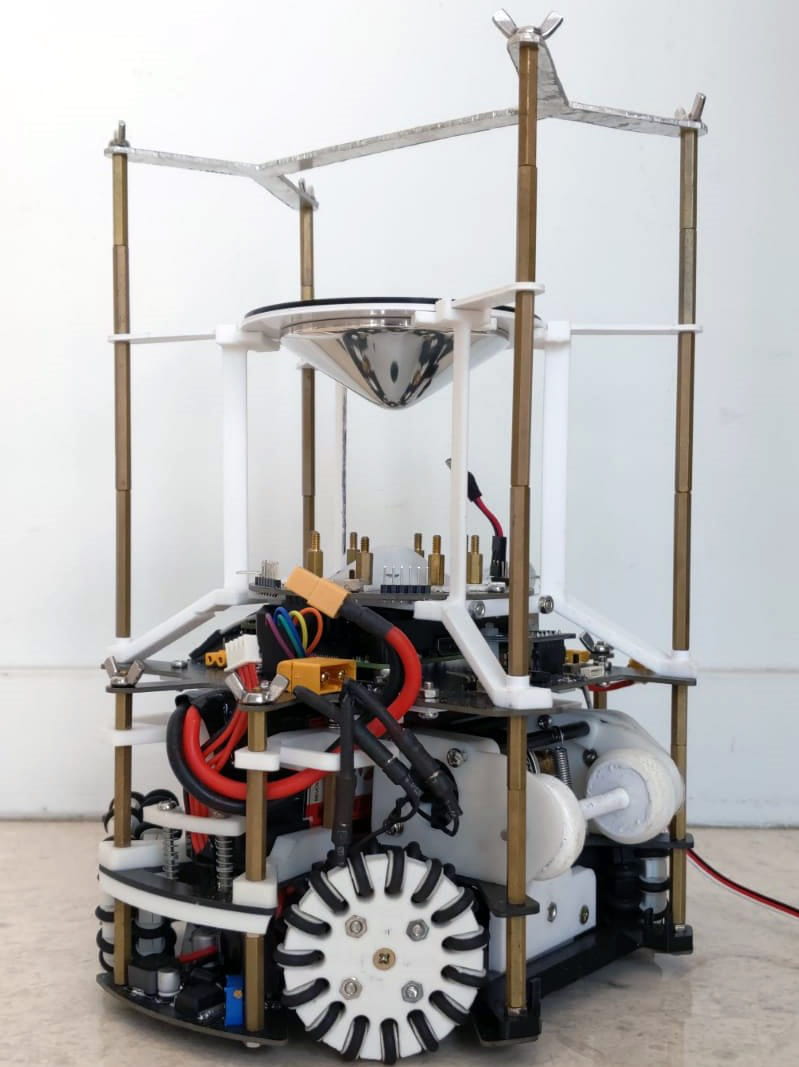
Mounting
Support Structures
The final step after making the mirror is to mount it properly. A huge majority of RoboCup teams mount their mirrors using a clear acrylic tube. However, we did not want to use this method because
- Our mirror had a non-standard diameter, which meant no commercially available acrylic tube could perfectly fit our mirror
- An acrylic tube would require a special miter saw in order to cut it since it was extremely brittle. We do not own a miter saw and we had to get permission to use a university’s (SUTD) lab in order to cut these tubes in the past, which was quite troublesome
- The tubes would accumulate scratches over time so the image produced will become less clear too
Thus, we sought inspiration from the RoboCup Middle-Sized League (MSL) teams to see how they mounted their mirrors. A paper regarding catadioptric systems in MSL (Section 4) showcased a mounting technique using three thin stands that minimised the areas the image is blocked.
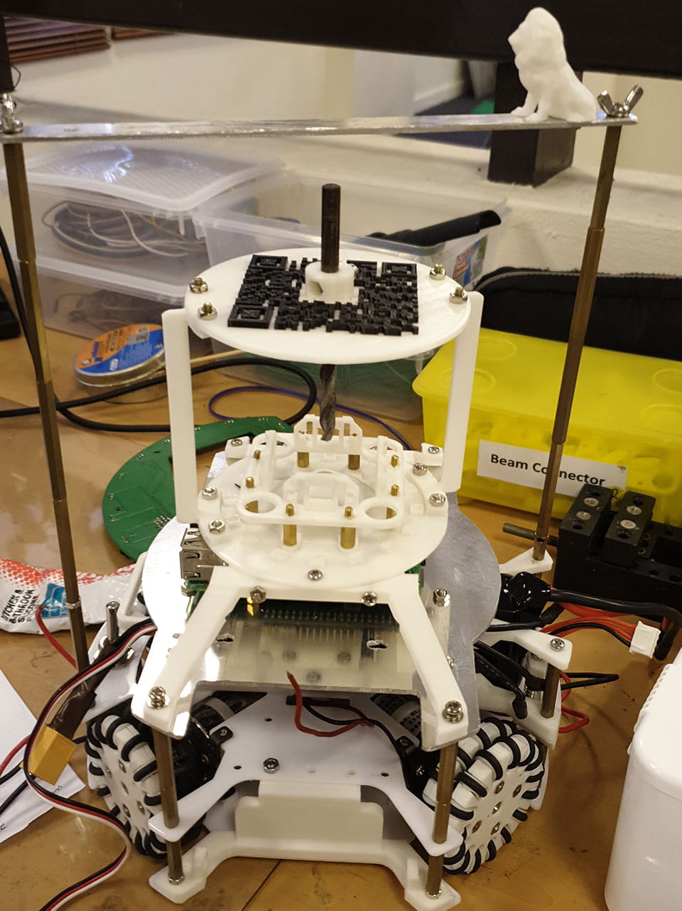
We adapted this idea and came up with our first mounting method with three 2 mm thick stands. 2 of the stands on the sides aligned with the handle’s copper stands while the third one sat perpendicular to them at the back.
We never actually physically built the 3 legged stand because the 4th layer mock-up that was 3D printed only had screw holes for 2 legs (translation: we were too lazy). However, just looking from the mirror plate being mounted on the 2 legs, it was clear that the 3 legged mount would be no better. Due to the sheer mass of the mirror (close to 200 grams!), whenever the robot was moving, the mirror would sway back and forth excessively, distorting the image ouput. The legs, being thin in order to avoid blocking too much of the iamge, were way too flimsy to support the mirror.
At about the same time, we noticed that the 2 long copper stands that supported the handle were starting to bend. As such we decided to make a 4 point connection for the handle and use those 4 points to hold up the mirror plate!
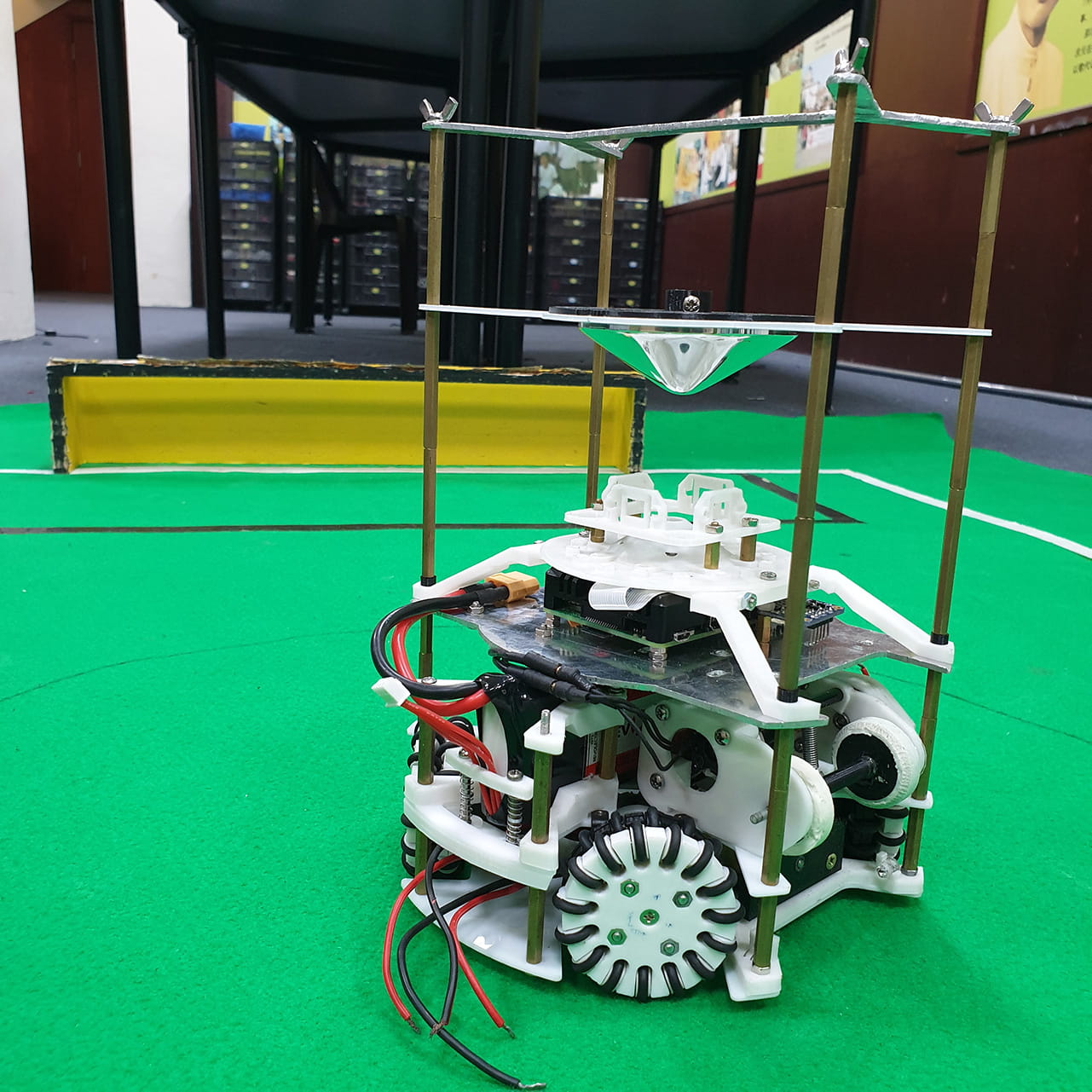
But then, after a few months, we realised that the mirror plate was starting to sag under the weight of the mirror. To fix this, an additional 4 stands extending from the trapezium mounts gave the mirror plate the support it needed. These 4 stands aligned perfectly with the 4 copper stands for the handle, and had a cradle like shape at the top for the mirror to snap in place. With that, our current 8 point support structure was born.
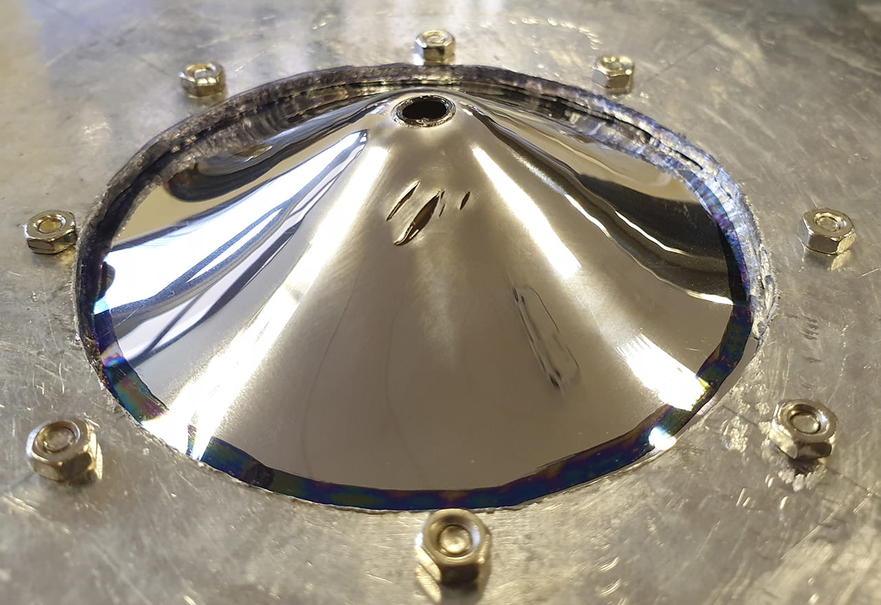
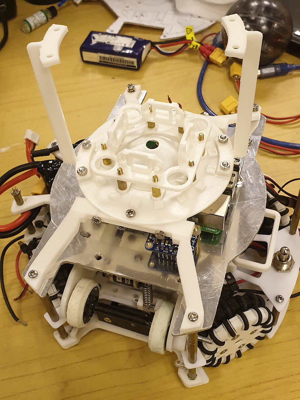
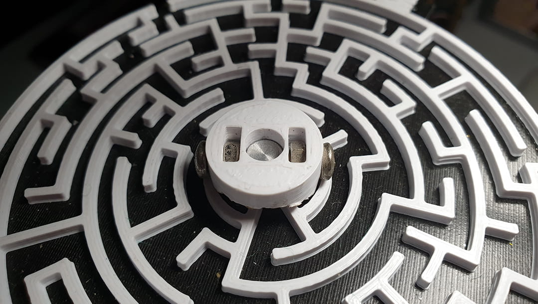
Mirror Plate
The mirror plate holds the mirror and it is what the support structures are actually supporting. The mirror plate uses the 6 mm diameter extension at the top of the mirror to hold it in place.
The mirror is placed through the centre hole of the mirror plate and a 3D printed mounting hub holds it in place. The mounting hub works by having an embedded nut with a screw, such that when the screw tightens, it moves inwards to the mirror stub, clamping it down.
The mounting hub design had a single sided screw hole, but we realised the mirror was so heavy that it started drooping on the side that was not screwed in place. Hence, we now use a double sided mounting hub which reduces the mirror’s drooping.
In addition, when the 8 point supporting structures were added, the mirror plate was thickened from 2mm to 3mm to further strengthen the 4 prongs.
Also, the mirror plate has a maze at the top which fits a 2mm ball bearing because why not? 🙃