General Information
Robot Size
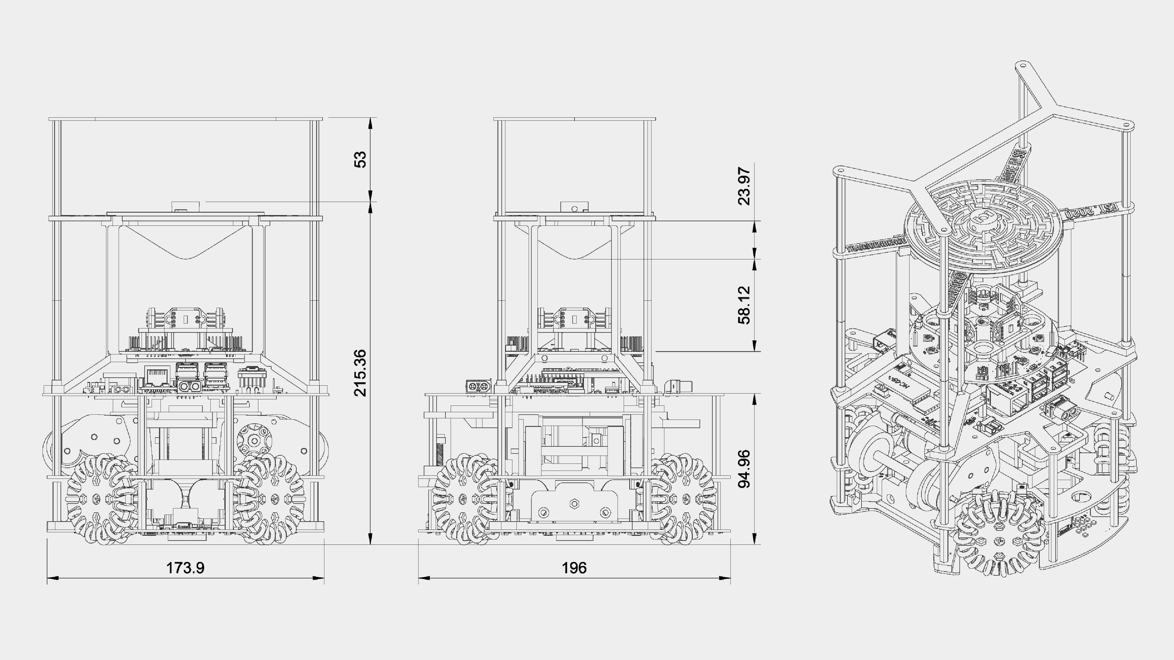
Our robot’s dimensions fit within a cylinder of diameter 200 mm and height 210 mm. The diameter of the robot was intentionally made to comply with the 2021 rules such that it did not have to be redesigned again. To fully fit within the 200 mm height limit for 2021, the mirror just has to be lowered slightly with no major changes required. The robot was not designed to fit the 2022 rules (180mm diameter) directly since we felt the size disadvantage of 40mm would have been too much.
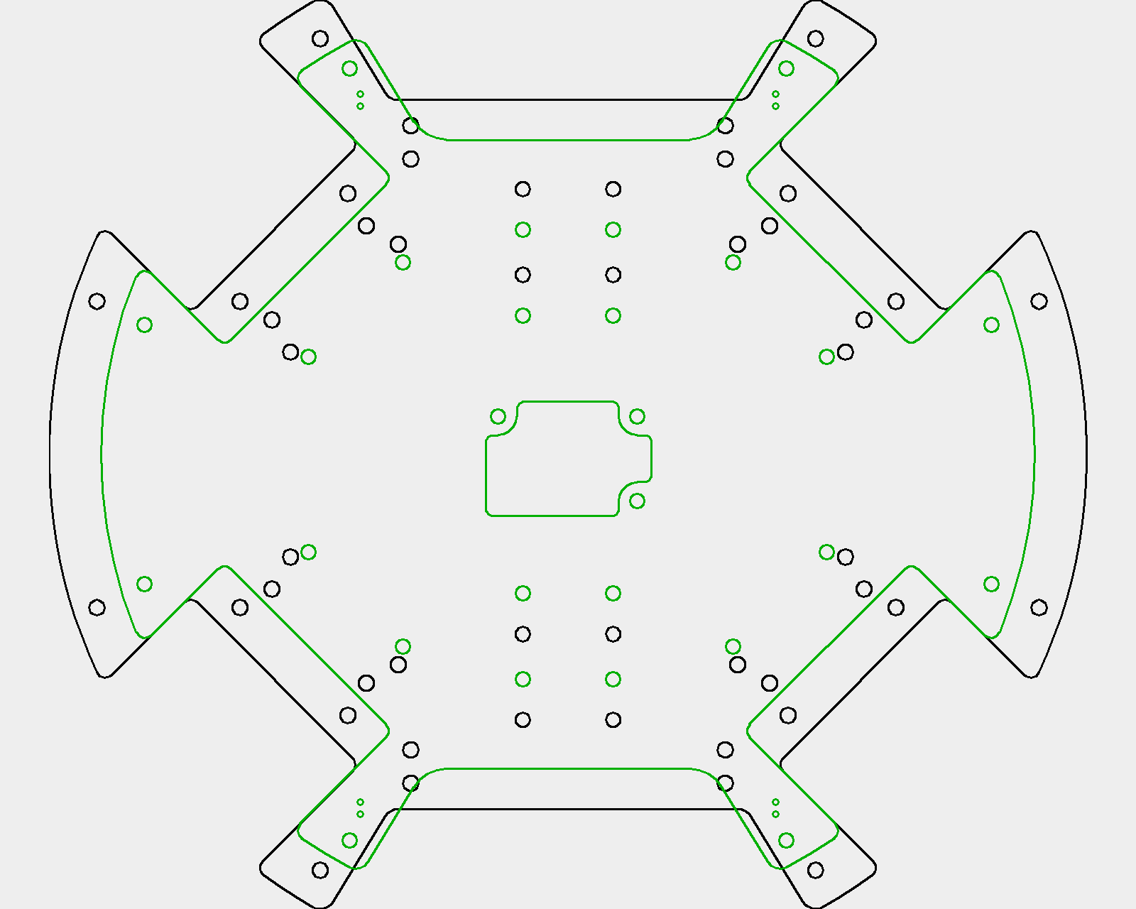
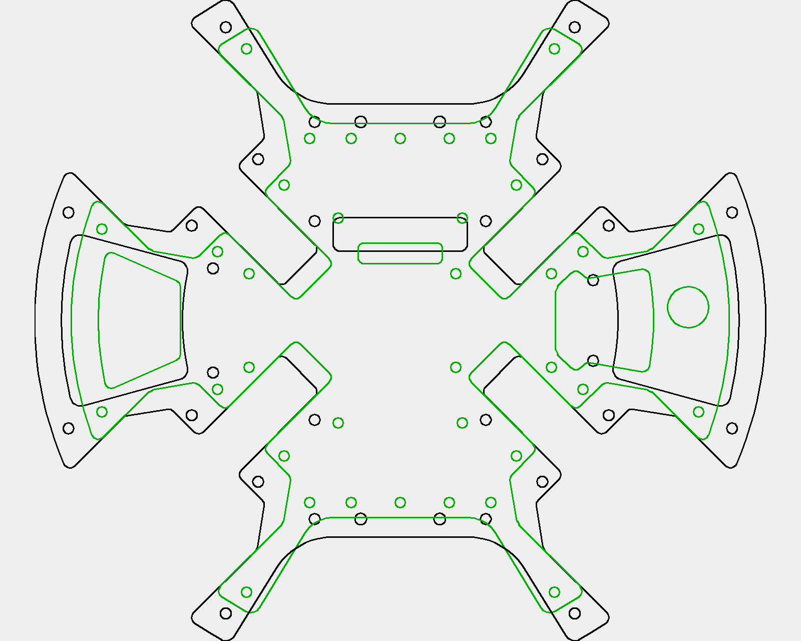
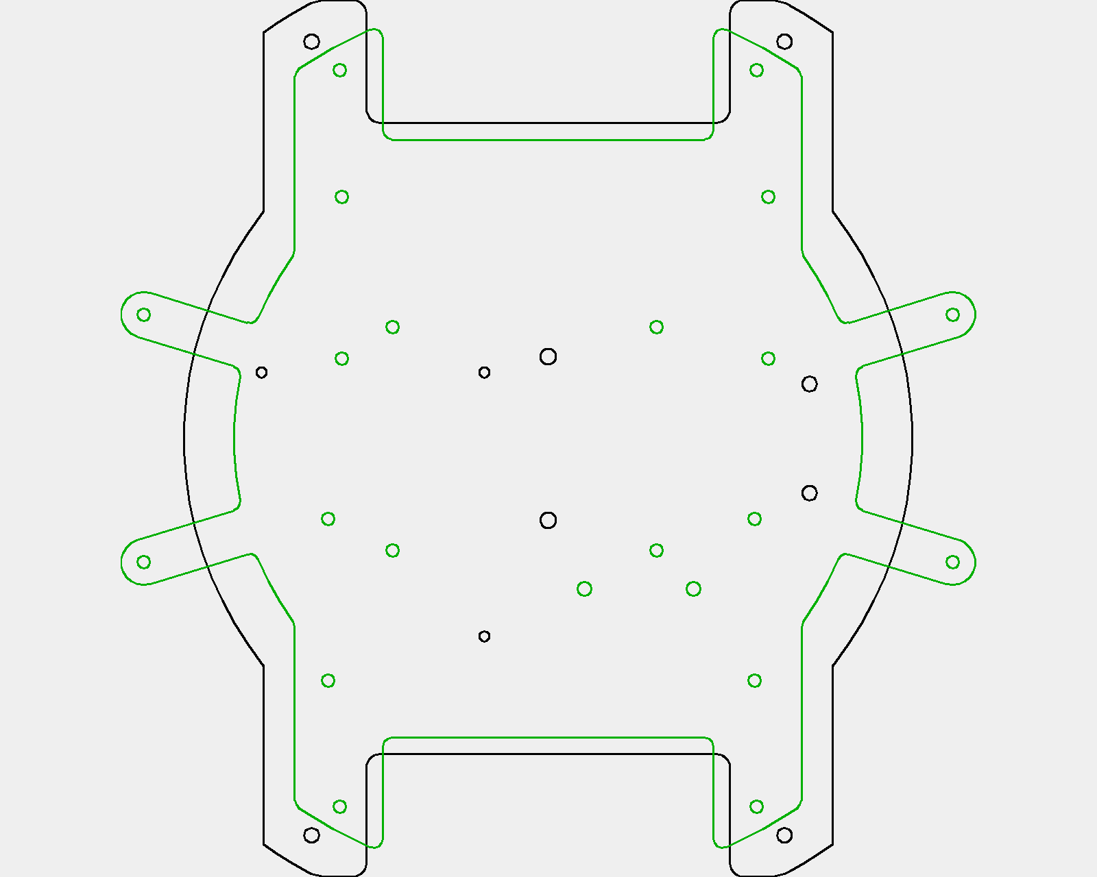
The process of adapting our 2019 robot to a smaller size was actually quite straightforward, albeit more tedious than what we initially expected. Instinctively, we considered simply offsetting the original 2D layer profiles, but that would not work since the catchment area sizes and screw hole positions would be completely off. Besides, there were a few fixes to the layer designs that we wanted to implement anyway. Thus, the new layers were constructed from scratch by redrawing over the original layers, using the orginal designs’ angles and lengths as a guage to keep the new design somewhat similar. The process of redesigning, sawing and assembling the first 3 layers for prototyping took only about a week.
Identical Robots
We decided to build both our robot’s to be exactly the same instead of having a separate striker and goalie design. Some of the benefits of having individualised vs identical robots that we considered were as follows:
- Individualised robots
- Better functionality for each role e.g. goalie could have different motor arrangements to allow for faster lateral movement
- More efficient use of parts e.g. a back dribbler would be unnecessary for a goalie robot
- Identical robots
- Robots could dynamically switch between attack and defense roles without compromising in performance for either role
- Only one robot design needed to be created, which would save a lot of time
In the end, we decided to go with identical robots, since its benefits were much more relevant to our plans.
Guiding Principles
When designing our robots, there were some overarching concepts that we adhered to, accumulated over past experiences, to ensure the robots were well-built.
Low CG
Having as low a centre of gravity as possible is one of the most commonly desired aspects of any mobile robot since it brings about much higher stability. Considering the high-speed, collision-filled nature of a RoboCup soccer match, the importance of a low CG extends far beyond simply preventing the robot from toppling. The video below showcases 2 instances of our older robot, which had quite a high CG, trying (and failing) to brake after detecting the white line.
It is clear that the robot was able to change its motors’ directions almost immediately upon detecting the white line. However, since it had a higher CG, when the braking force was applied, the turning moment about the front side of the base of the robot was larger. This increased the likelihood of the back wheels lifting up slightly, losing traction and skidding rather badly. This “wheel-lifting” problem is especially obvious in the second part of the video.
A more intuitive way to look at this would be from the free body diagram of a braking robot. Given a robot with CG at a higher point C1 vs a lower point C2, it can be seen that W2 is closer to the “lifted” side, giving the wheels on that side of the robot “more traction” than if it were W1.

Free body diagram of braking robot as single object
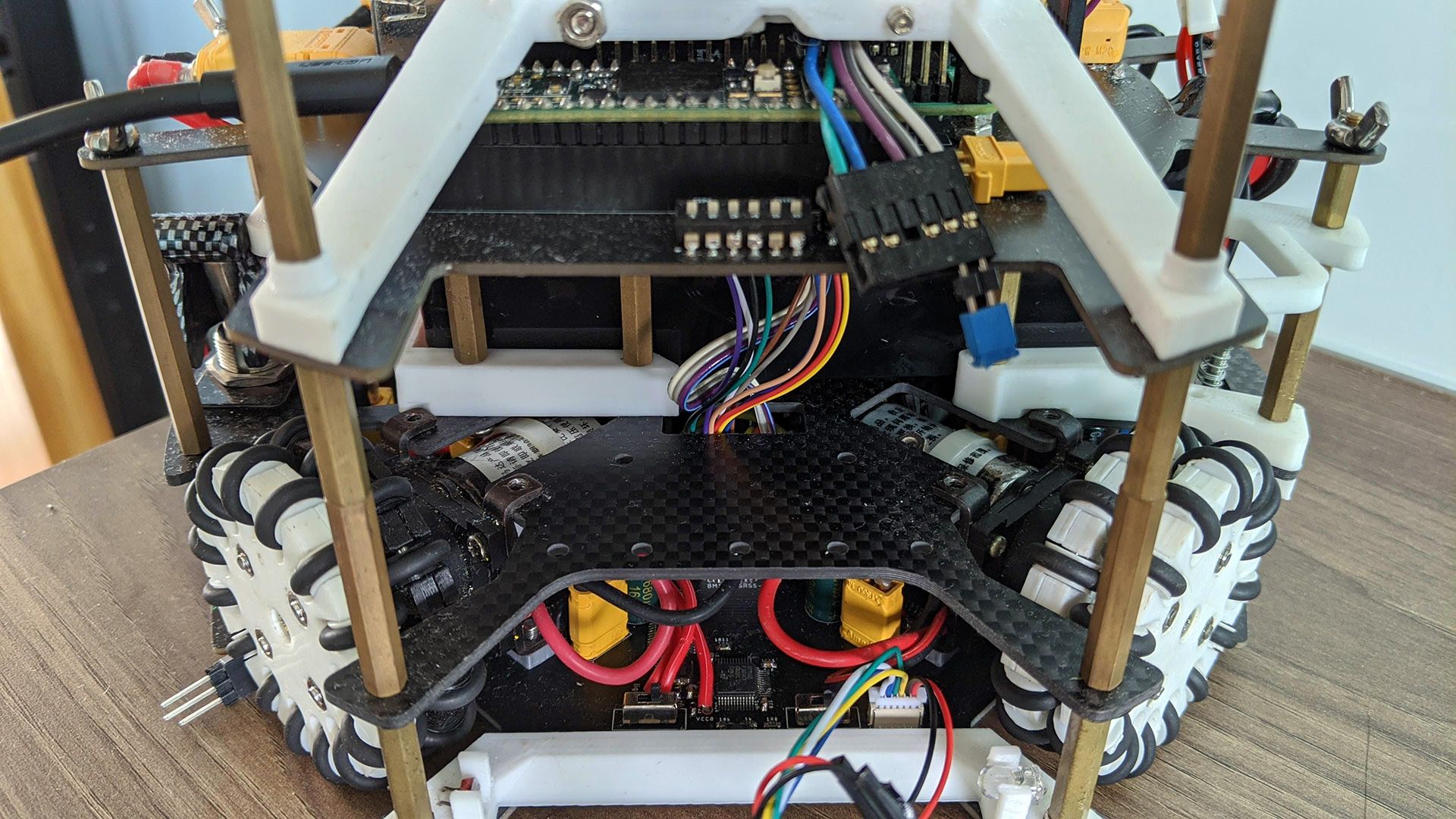
Hence, having a low CG is crucial in ensuring the robot can accelerate quickly in a reliable manner, allowing for more consistent motion across the field. Some low CG features of our robot include:
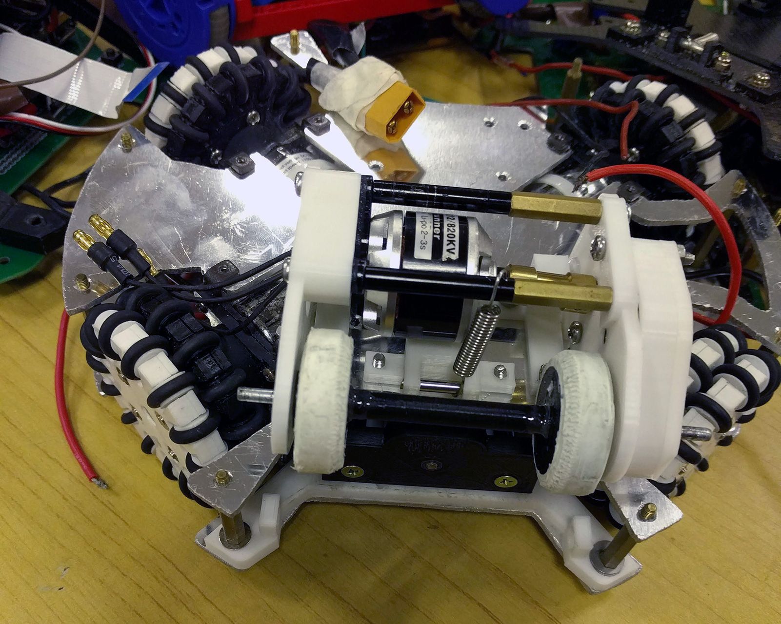
- All the heaviest components are concentrated among the first and second layers
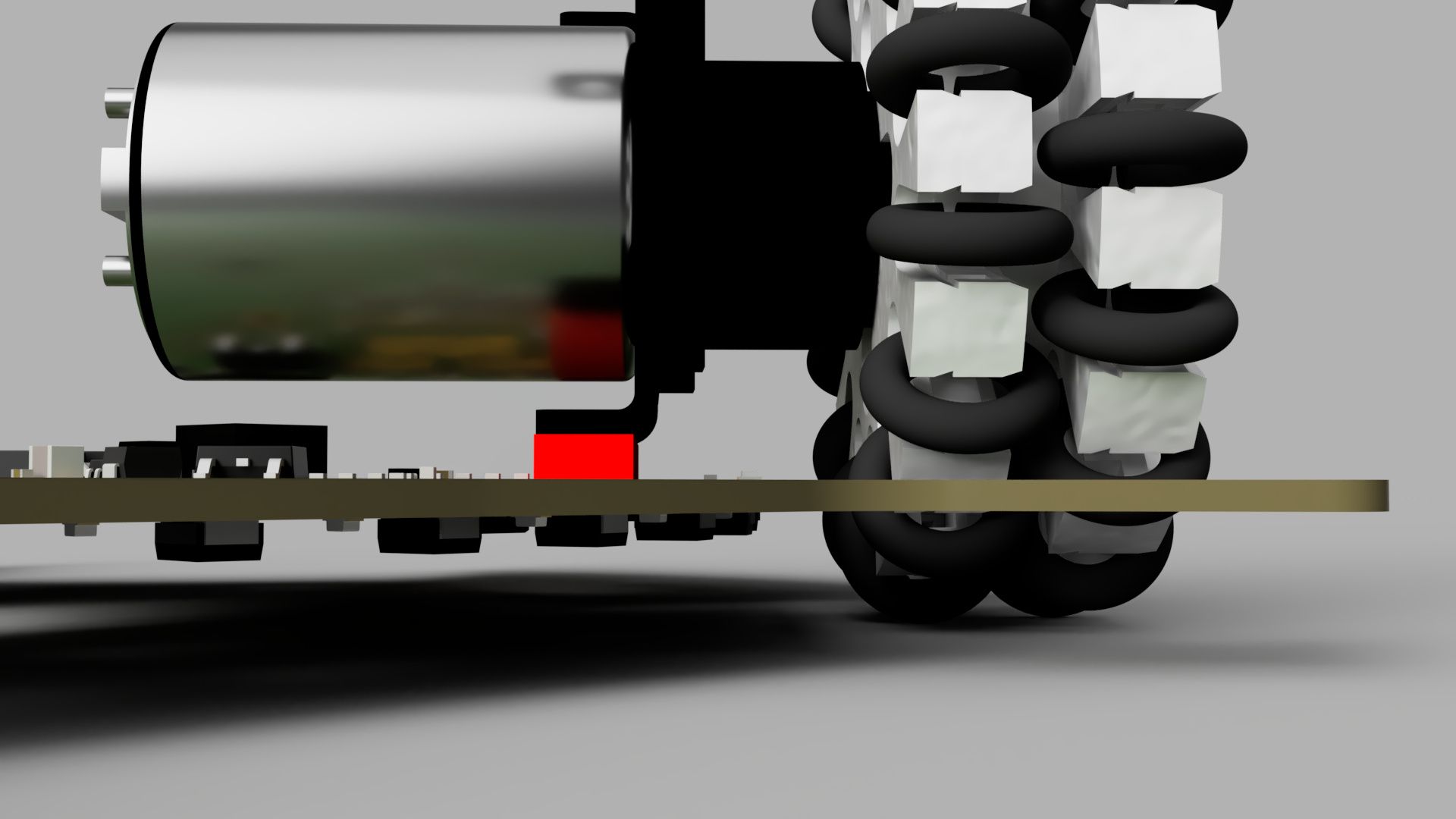
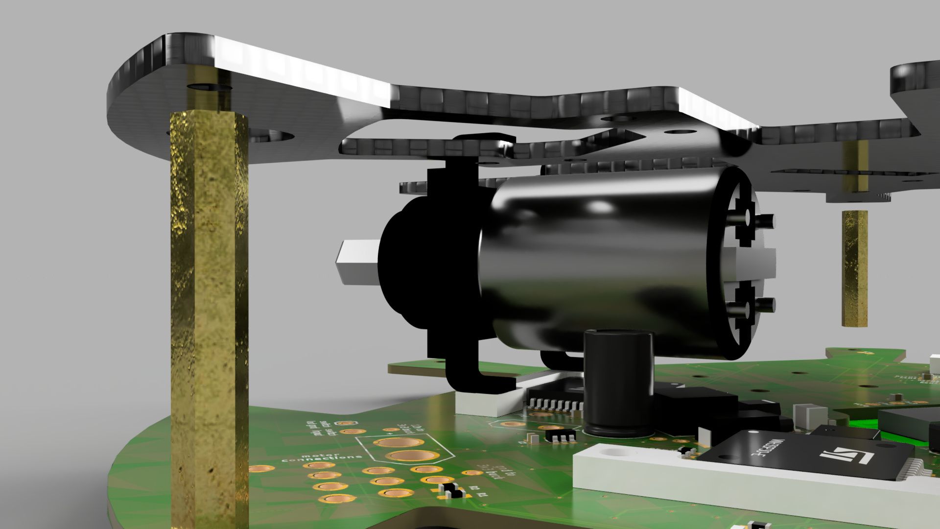
- A spacer was placed under the motors, which elevated the wheels and lowered the whole robot (the distance between the ground and base plate was less than 6 mm)
- The second layer had many cutouts such that it could fit under the upper angle bracket of the motor, lowering the height of the heavy battery
Weight Distribution
There are 2 factors to weight distribution: even distribution and centralised positioning.
Even Distribution
Even distribution of weight is where weight of different objects of the robot is apportioned equally among all of its points. In other words, the centre of gravity should be as close to the XY centroid of the robot. This is necessary in ensuring that the forces acting on each wheel is equal, allowing all wheels to have the same effect on the motion of the robot, thus making the movement of the robot more accurate. This can be achieved by making the robot as symmetrical as possible.
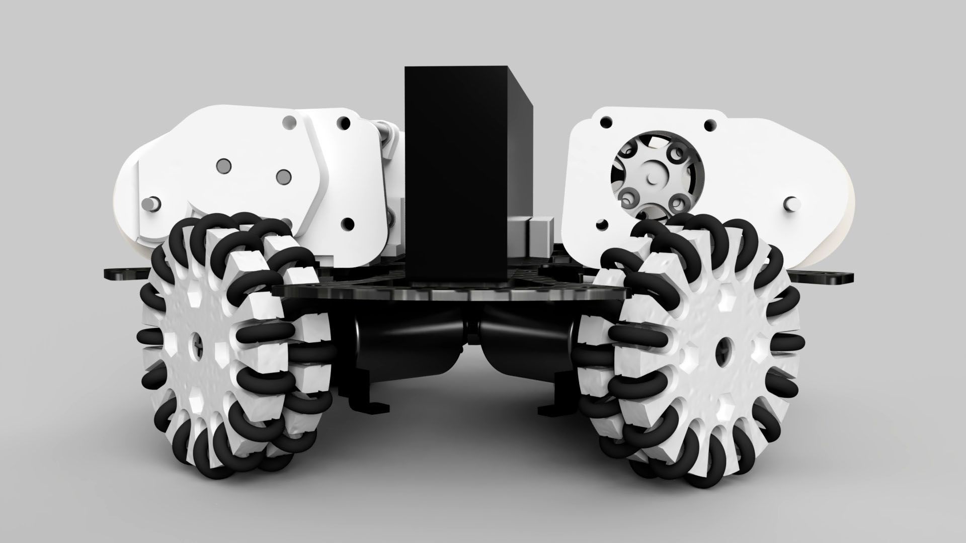
Perfectly even weight distribution was impossible for our robot since we were only using 1 solenoid that faced the front. Nonetheless, this solenoid was placed as far back as possible such that it would be nearer to the geometric centre, while the robot was designed to be mostly 180 degree rotationally symmetrical.

180 deg rotational symmetry
Centralised Positioning
Centralised positioning of weight is where most of the weight is placed near the centre of the robot. This decreases the moment of inertia of the robot, which makes the amount of torque needed to change the angular acceleration of the robot lower too, allowing for faster rotational motion of the robot. This can be achieved by placing objects as close to the centre of the robot as possible.
For our robot, some heavy objects such as the dribblers and solenoid had no choice but be placed further out because of the nature of their functions. However, the remaining heavy objects were all placed closer to the middle. The battery lays directly in the middle of the second layer, while the motors were “pushed” inwards as far as possible. The smaller size of the robot also helped decrease its moment of inertia.
Here is a video of our robot spinning on the spot with the motors at roughly 40% power. There are some oscillations in its movement due to the weight imbalance from the solenoid, but its overall position does not drift much, which shows it has rather good weight distribution.
Lightness
Robots should be as light as possible. While this might seem disadvantageous since a heavier opponent could easily push you around, the use of sheer force to overpower an opponent has largely been discouraged, especially with recent changes in the rules that basically forbids all forms of pushing.
A robot with a smaller mass has less inertia, which means it is less resistant to changes in its motion. In additon, by Newton’s second law of motion, a robot with a smaller mass requires less force to impart the same change in acceleration since F = ma. Thus, having a lighter robot would allow it to accelerate quickly in all directions, allowing for faster translational motion. To keep the robots relatively light, we:
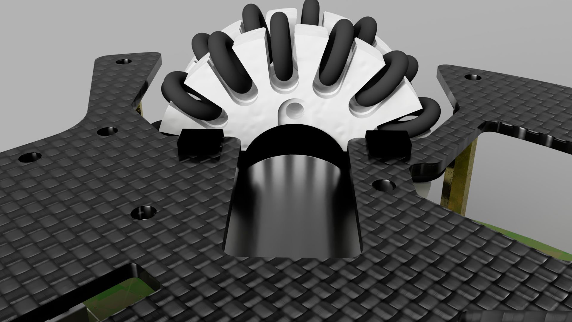
- Used carbon fibre for our second layer plate since it is a material with one of the highest strength to weight ratio
- Used 3D printed parts extensively, with infill of 15% to 20%. While higher infill percentages do contribute to greater part strength, in our experience, 15% infill already provides sufficient strength while being much lighter.
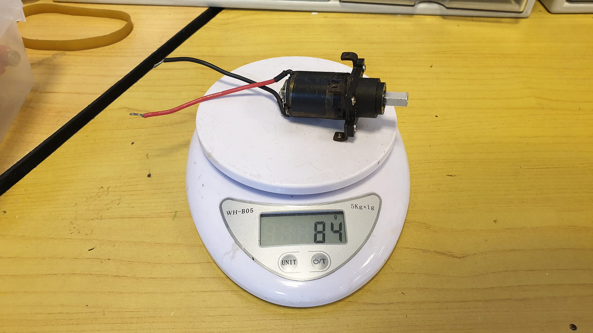
- Chose motors which had very high power to weight ratio
Sturdiness
Every robot needs to be sturdy in order to be durable and resist damage, especially in Soccer Open where 2 kg spinning discs are constantly crashing into your robot. Our robot is built to be very stable since
- There are 8 points of connection between the robot’s main layers using strong hex brass standoffs
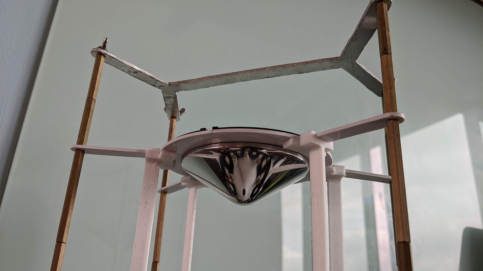
- The mirror plate also has 8 points of support to prevent it from flexing under the mirror’s weight
- The motors are wedged between 2 layer plates, ensuring they do not flex inwards under the robot’s weight
Modularity
A modular design is a design that comprises multiple independent parts, which is beneficial since different aspects of the design can be easily improved/switched out without much effort. With a RoboCup robot, a design with a reasonable amount of modularity makes mechanical fixes or part replacements due to wear and tear a much less tedious process. However, it is important that sturdiness is not sacrificed for modularity (e.g. making a part easily detachable might also make it weakly connected).
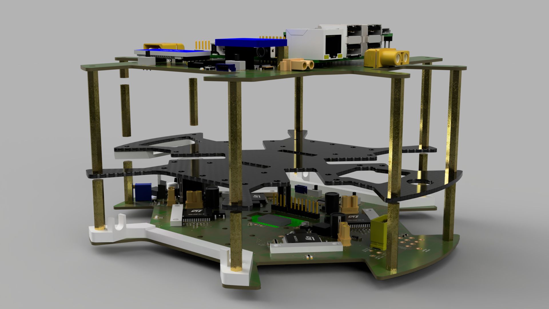
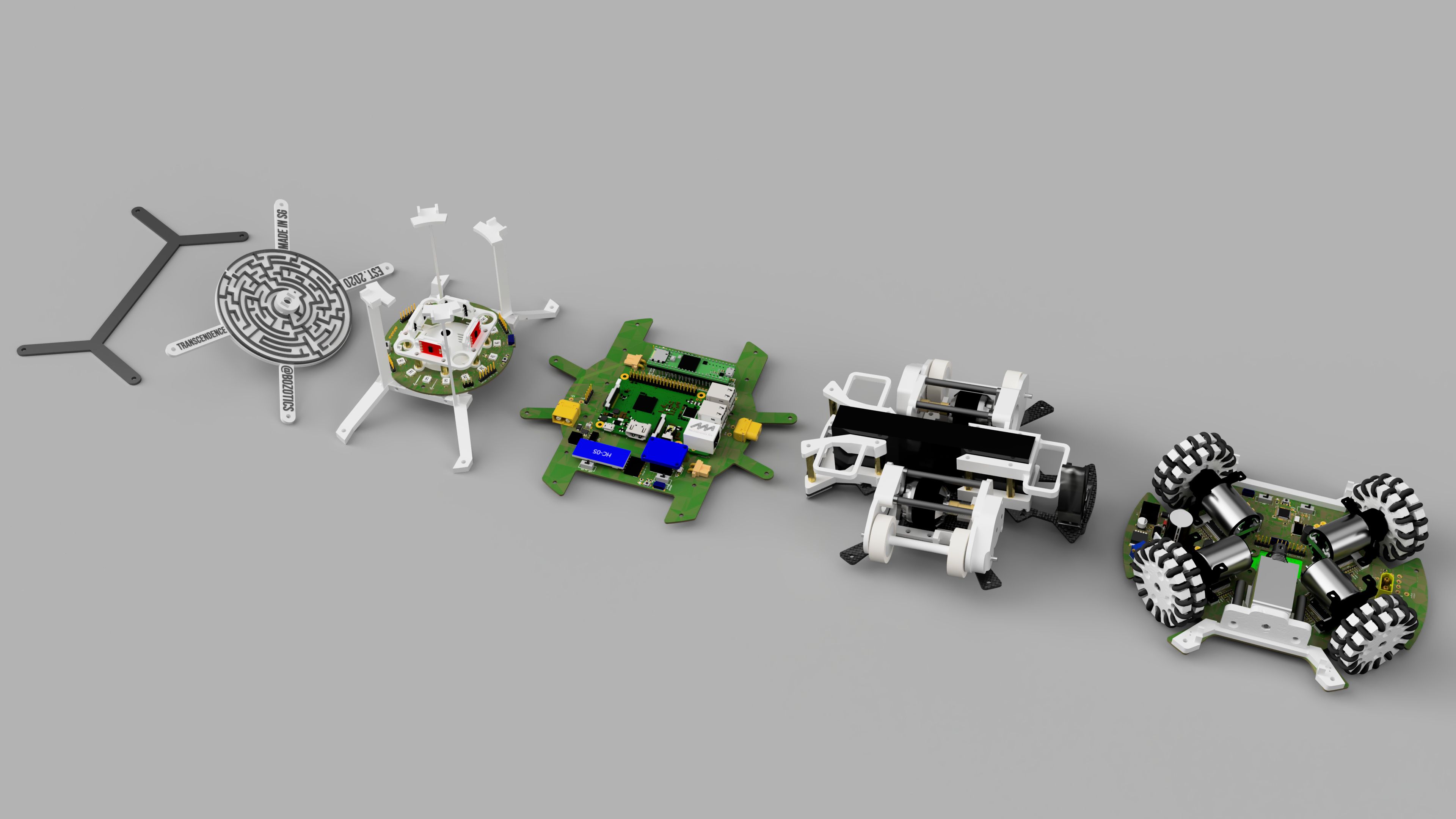
Our robot is quite modular in terms of the sectioning of our robots into different layers. Each layer can be assembled individually, before bringing it all together. The image below shows the main sections (from left to right): handle, mirror, camera module, 3rd layer PCB, 2nd layer carbon fibre plate, 1st layer PCB.
CAD Software
The CAD software used to design our robots was AutoCAD. The reasons why we chose AutoCAD over the more commonly used Fusion 360 is because:
- AutoCAD has always traditionally been our go-to CAD software since we used it to create the 2D profiles for our layer plates, and naturally, when extending from there onto a full 3D model of our robot, we simply continued within AutoCAD itself
- AutoCAD has much more versatile camera placements and rendering options, needed for making our mirror
- AutoCAD is a more “bare bones/stripped down” CAD software, using a command line and direct modelling workflow, which made it easier to learn
Nonetheless, the parametric workflow and added features like simulation analysis that Fusion 360 has can certainly offer many benefits and will be integrated into our designing process in subsequent years.