Drive System
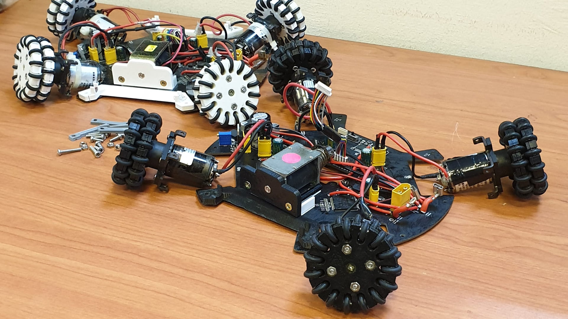
The drive system is the most important part of the robot, directly dictating the degree of mobility of the robot. A 4-wheeled holonomic drive was utilised to give our robot full control over both its linear and angular velocity. Much consideration was also put into the individual components to produce the most effective drive system.
Motors
The motor we use is the JMP-BE-3561 model by JoinMax (Website & Datasheet). We first bought this motor back in 2018, which was also the year where this motor made its international debut with lightweight champions, LJ Stand (Poster). We used this motor for internationals in 2018 too (Poster), and this motor has only seen increasing adoption in the 2019 season.
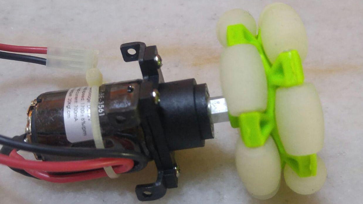

Out of the box, this motor comes equipped with a planetary gearbox and is built with an angle bracket frame for easy mounting. This is an extremely high-powered motor with a no-load speed of 1700 RPM and a stall-torque of 20 kgf·cm, which translates to about 1.96 Nm. To understand how insanely powerful that is, here’s a comparison table of its specs to other similarly sized motors from more popular brands. (Notes: no load speed and stall torque are calculated assuming 100% gearhead efficiency, the price is calculated from unit price, and all motors have a nominal voltage of 12 V)
| Motor | Diameter (mm) | No load speed (RPM) | Stall Torque (Nm) | No load current (mA) | Weight (g) | Price (SGD) |
|---|---|---|---|---|---|---|
| JoinMax Motor | 24.5 | 1700 | 1.96 | 700 | 80 | 120 |
| Maxon A-Max Motor 11037 with Maxon 4.8:1 Gearhead 166156 | 26 | 1706 | 0.385 | 57 | 220 | 348 |
| Maxon RE Motor 339150 with Maxon 5.8:1 Gearhead 166157 | 25 | 1658 | 1.55 | 68.1 | 220 | 480 |
| Pololu Metal Gear Motor with 9.68:1 reduction | 25 | 1030 | 0.314 | 300 | 82 | 31 |
| CHR-GM25-BK370 with 1:20 reduction (Another China motor we own) | 24.4 | 980 | - | 600 | 85 | 6.40 |
It is clear that no motor even comes close to the JMP motor in terms of offering high speeds, high torque, low weight and relatively cheap pricing. However, there is one major disadvantage which is the incredibly high no load current. This motor is a giant power suck and thus, heats up very quickly too. On the other hand, this motor is simply too highly rated for us to ever use its full capabilities in a controllable way, with the fastest speeds used set at about 50% of the full speed. While this means a lot of the motor’s capabilities are “wasted”, it also means that the negative effect of overheating is somewhat curbed.
A good alternative to our JMP motors would be Maxon’s RE motor series, but a single motor with gearhead combo costs 480 SGD without shipping so that’s definitely not happening anytime soon…🙃 (yes, we tried requesting for sponsorship under Maxon’s Young Engineers Program before but they didn’t even bother replying us…) Hence, we concluded that the JMP motors were our best option after considering all the factors above.
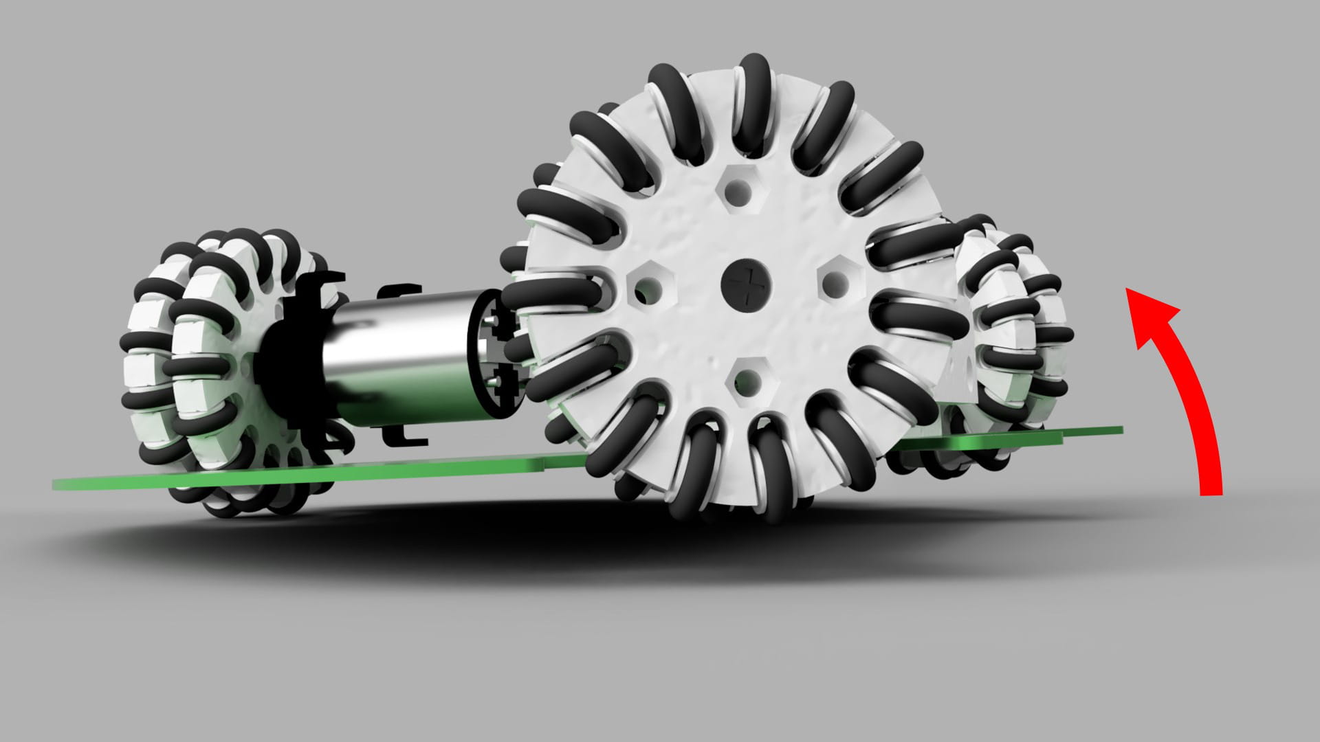
Wheels
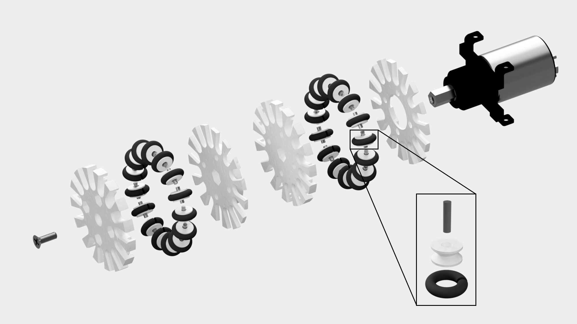
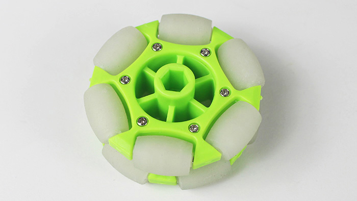
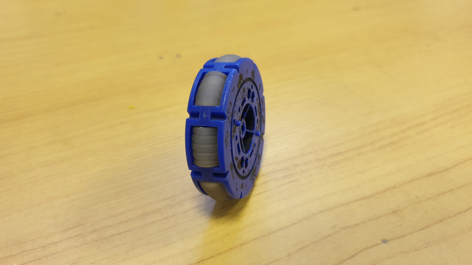
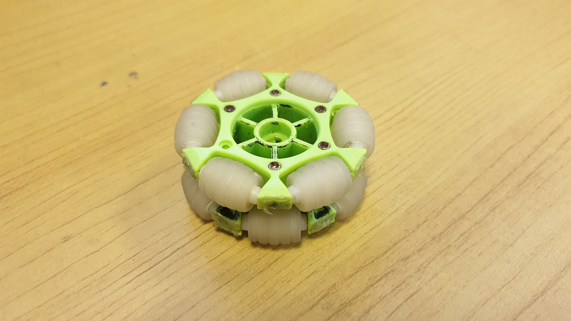
Our wheels are mostly made up of 3D printed parts. We made the omni-wheels doubled layered instead of single layered so that our robot has greater traction on the field, especially since the mini rollers are quite thin. Each omni-wheel layer contains 15 3D printed mini rollers, which has an hourglass shape.
Each mini roller is fitted with a NBR O-ring (6 mm diamter, 3 mm thickness) that acts as the tyre. This O-ring has to be stretched a little to wrap around the outer section of the mini-roller before falling in place along the recess of the roller.
Also, a dowel pin (2mm diameter, 8mm length) is fitted through the middle of the roller to act as an axle. The centre hole of the roller is slightly smaller on one side such that the dowel pin has to be force through, ensuring that the roller remains rigidly connected in place since its the dowel pin that is spinning freely, not the roller.
Each omni-wheel layer is made up of one thick and one thin 3D printed plate. The thicker plate contains rectangular indents where the mini rollers fitted with the dowel pins will sit in. The size of these rectangular indents took quite some trial and error since their tolerances are very small; they had to be just loose enough to allow the dowel pins to spin freely but just tight enough to prevent it from jittering about too much. The thinner plate fits on top of the thicker plate to act as a cover.
Wheel assembly process
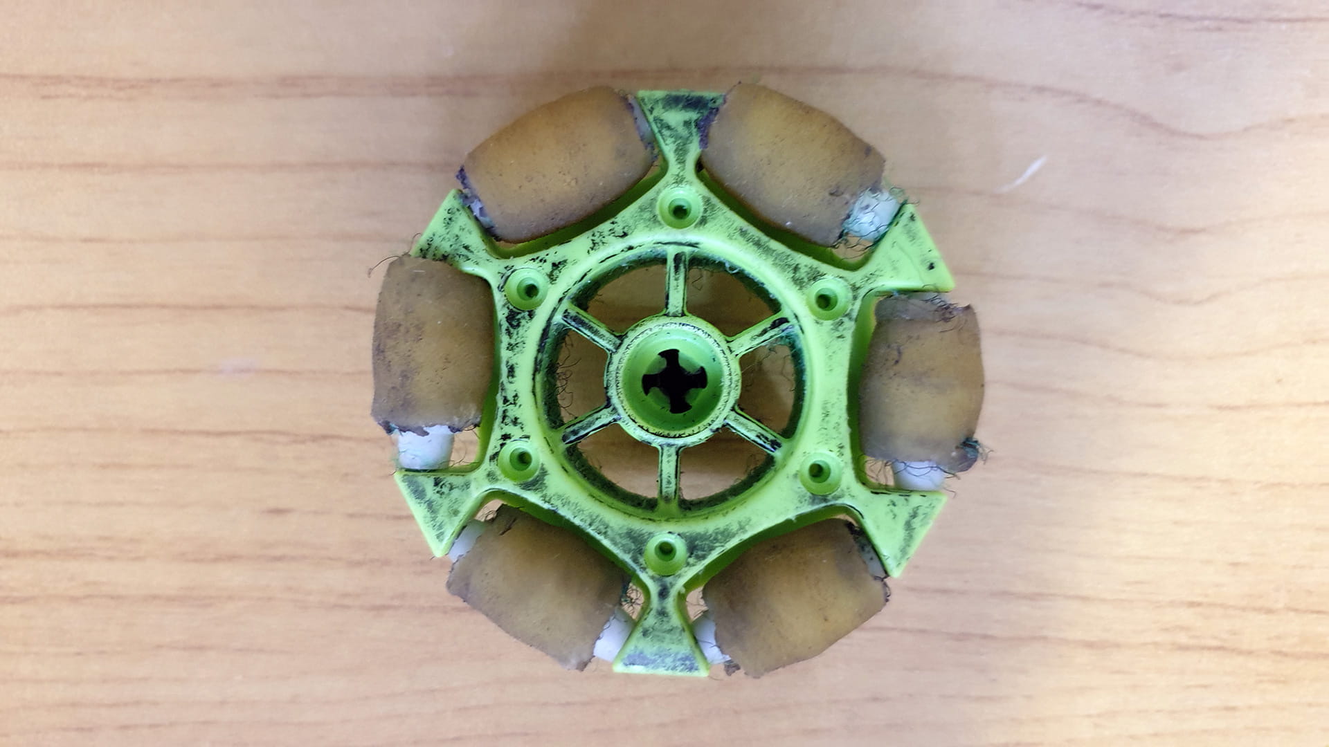
Backstory: These wheels were created to replace our JMP-BE-6059 wheels. The JMP wheels were actually quite good since it uses large rollers and is also double layered. However, the material of its roller is soft rubber, which despite having good traction, was not durable at all. These wheels were used by our RoboCup 2018 lightweight team and at the start of the competition, the wheels were almost brand new, but by the end, the rubber rollers were either breaking apart or had completely fallen off, leaving behind the raw plastic roller itself. Attempts to make a Frankenstein wheel out of another JMP wheel (JMP-BP-1261) which used a harder rubber were tried, but they were much less effective since the harder rubber had little traction. Hence, the need to create our own, more durable wheels arose.
Positioning
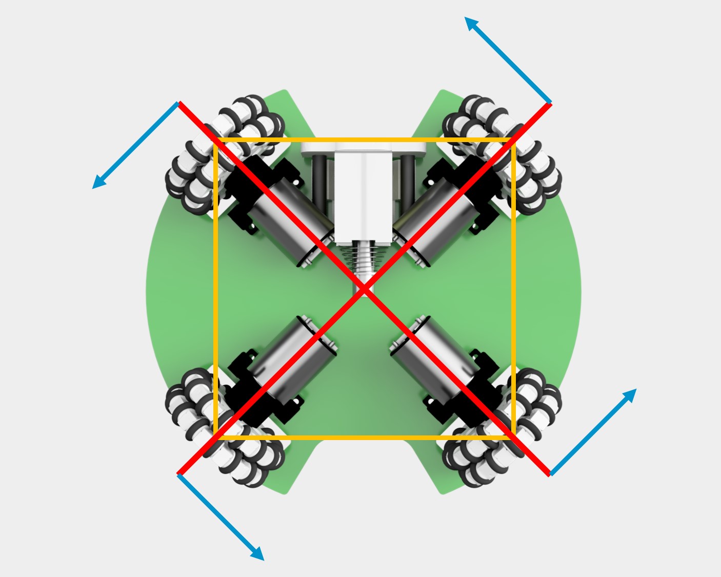
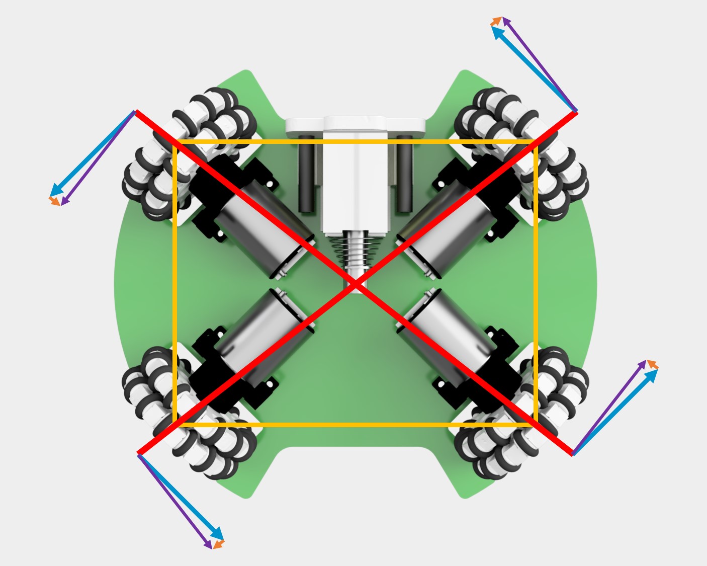
The motors’ angles relative to one another can affect the maximum speed of the robot when moving in certain directions. For example, a motor combination with the front angles being larger will result in faster forward movement. Since we wanted the robot to travel equally fast in all directions, as well as to make our holonomic calculations easier, we decided to arrange the motors in a 90 degree fashion. However, arranging them simply in a 90 degree cross would make the catchment areas very small and the solenoid has to be forced in place to fit between the motors. Thus, we came up with a “split cross” arrangement, where the motors were moved apart horizontally while preserving the same angle.
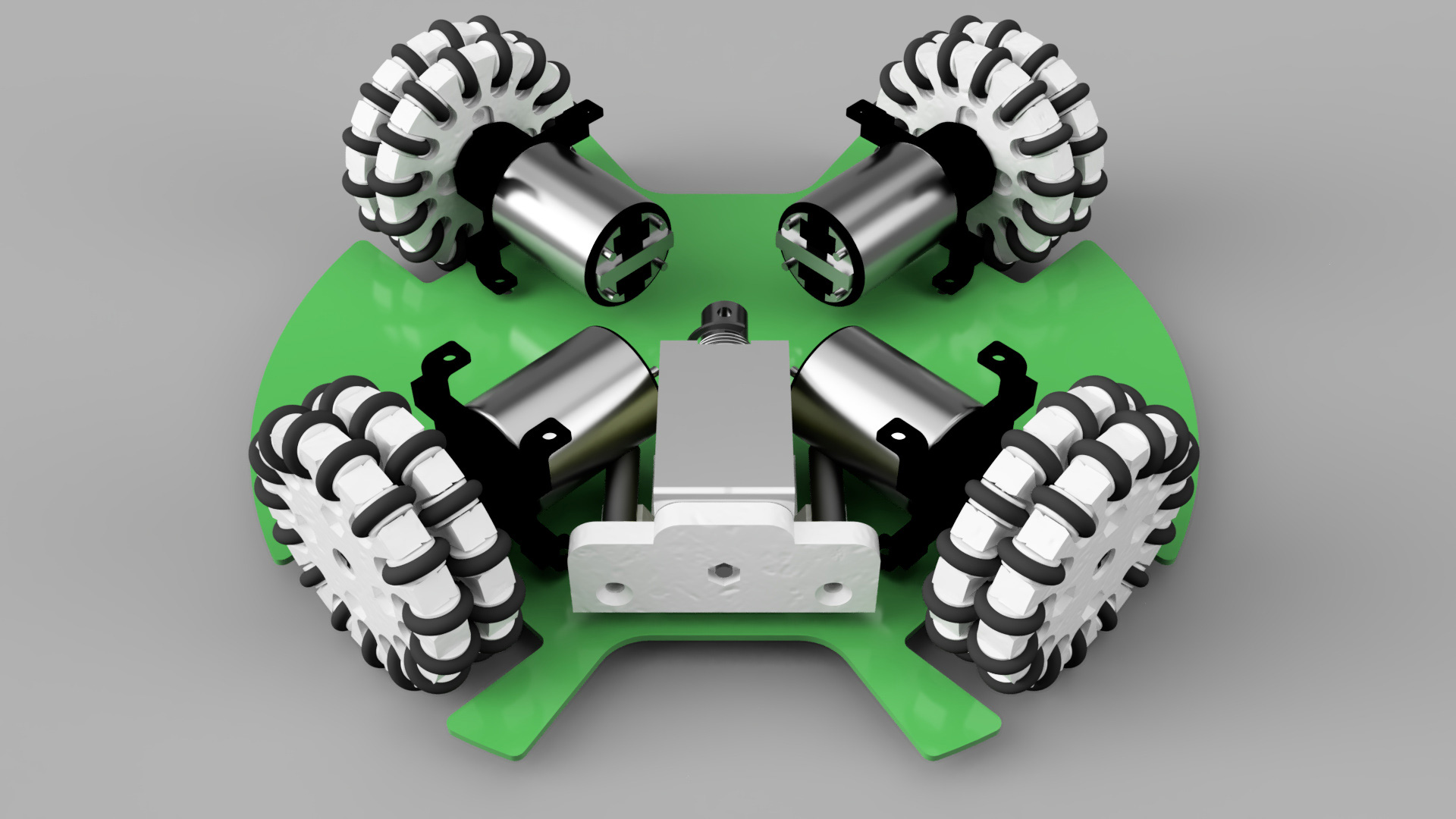
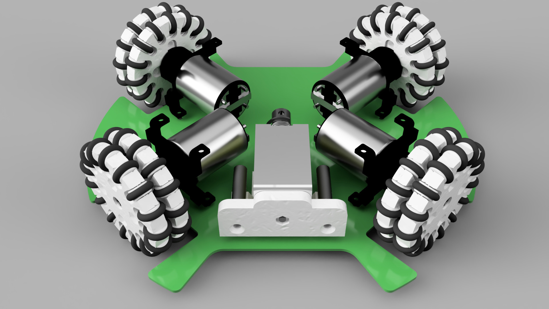
This arrangment provides the much needed extra space and expands the catchment area size, while resulting in minimal change in the robot’s locomotion characteristics. In the vector diagrams below, the blue vectors represent the wheels’ velocities, which is of the same direction and magnitude for both arrangments. Thus, linear motion remains the same. However, with the split cross, the wheels are not perpendicular to its displacement from the robot’s centre. Thus, only the perpendicular component (purple arrow) contributes to the robot’s angular velocity, which can be easily accounted for in the calculations. (More details about holonomic movement can be found in the Programming section)
3 vs 4 Wheels
In theory, only a minimum of 3 wheels are needed to produce a holonomic movement. (This is because with 2 wheels, if they are directly parallel to each other, there is only one translational degree of freedom. Otherwise, if they are in any other configuration, as long as they are moving at different speeds there will always be a net angular velocity on the robot.)
There are a number of RoboCup teams who do choose to employ a 3 wheel holonomic drive, particularly in lightweight due to weight constraints. However, a 3-wheel drive has many, many problems, especially considering the dynamic nature of a match.
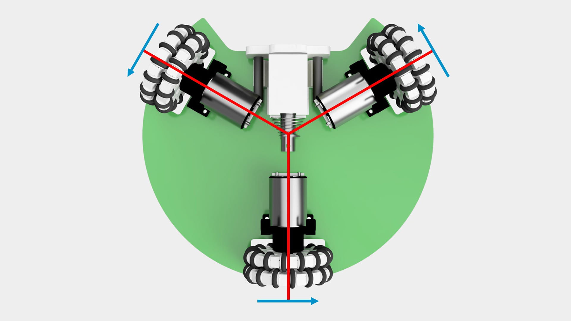
Firstly, it is inefficient. A 3-wheel drive in RoboCup must be arranged in the Y-formation to give room in the front for the catchment area. Thus, when moving straight (which is probably the most common direction), only the front 2 motors are being used to move the robot.
Secondly, it has much less traction, which reduces agility. Intuitively, with less wheels there would be less traction (especially if the forwards direction is only driven by 2 wheels instead of the typical 4). However, there is also the consideration of collisions. If a 3 wheel robot collides head-on with another robot (which happens all the time), the front 2 wheels will be lifted up momentarily. When this happens, there would be completely no motors driving the robot forwards, which is bad, really bad.
Thirdly, it is much more unstable. There is a further distance between each wheel as compared to a 4-wheeled robot, which increases the tendency for the robot to tilt. Also, since 2 adjacent wheels are now closer to the CG, there is a larger moment about the base of the wheels whenever there is a change in momentum. Both phenomena causes a loss of traction, which further exacerbates the previous problem.
Fourthly, the position of the back wheel prevents any chance of a double dribbler design. This. This is the deal breaker. 🙃
Therefore, it is without a doubt that a 4-wheeled robot is much more superior to a 3-wheel robot and there really isn’t any reason to go for a 3-wheeled design other than maybe to save weight.
But to become lighter in exchange for less traction? That would be the worst trade deal in the history of trade deals, maybe ever… :)