Dribbler
The biggest inspirations for our dribblers were from teams:
- EMM Soccer (2016) (Match Video): Double dribbler
- Input (2017) (Poster, Blog): General concepts
- Cat-Bot (2018) (Poster, Blog): Dribbler design
Theory
A dribbler works by having a fast moving roller that imparts backspin on the ball, which produces a constant backwards force on the ball for it to stay within the catchment area.
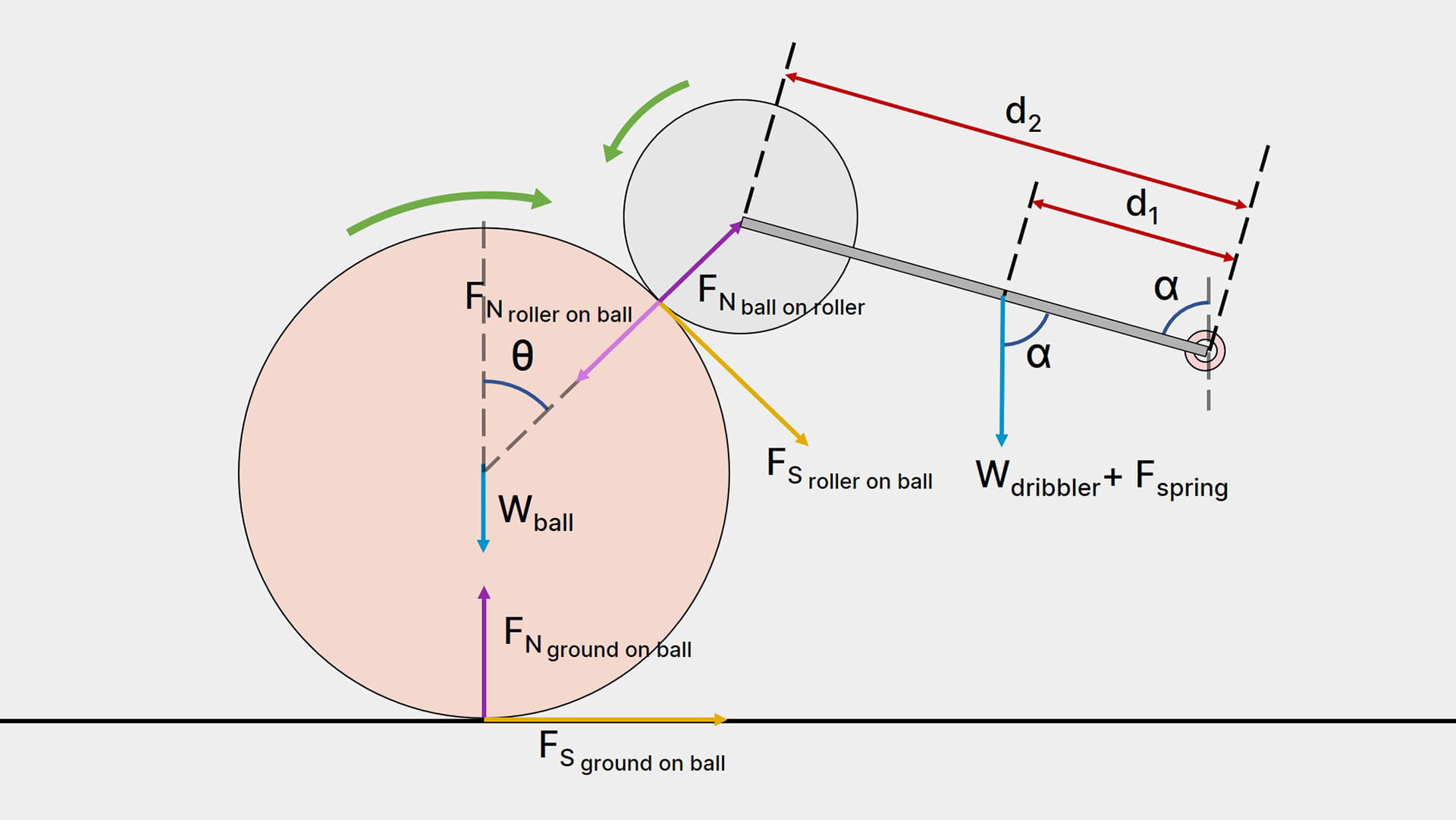
This is a simplified free body diagram of a dribbler. The dribbler module is condensed into a simple lever system and the force of the spring is assumed to come from the same point as the dribbler’s weight for easier calculations. To understand the effect of changing specific aspects of the dribbler intuitively with minimal math, read on; otherwise, jump to the mathematical approach section.
Roller Position
The angle of the dribbler’s rollers relative to the ball (value of θ) directly determines how well the dribbler holds the ball.
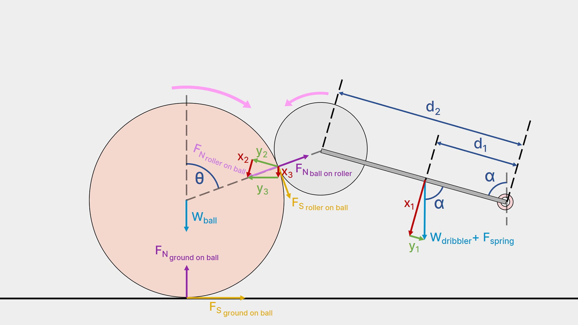
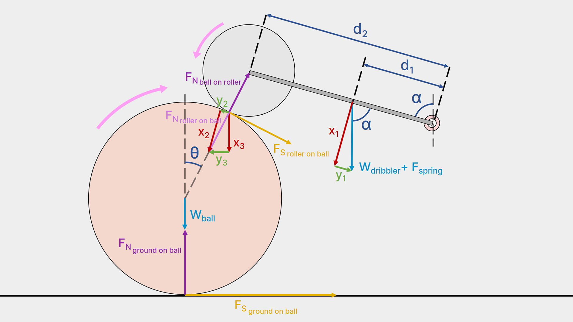
If the value of θ is smaller (rollers are positioned higher up the ball), assuming the pivot angle, α, remains the same, the normal contact force from the roller to the ball, FN:roller on ball, would increase. This is because the component of Wdribbler+Fspring that is perpendicular to the lever (red arrow, x1,), would result in a larger magnitude of the corresponding perpendicular component of FN:roller on ball (red arrow, x2).
Resolving FN:roller on ball into x3 and y3 instead, it is clear that the component perpendicular to the ground, x3, becomes larger. Thus, the normal force between the ground and ball, FN:ground on ball, increases in magnitude too.
Therefore, the friction between the ball and ground, FS:ground on ball, will become larger. This means that the higher the rollers are, the greater the backwards force generated into pushing the ball into the catchment area. However, the larger friction between the ball and ground also means more torque will be required to spin the ball i.e. it becomes harder to spin the ball.
The torque needed to spin the ball becomes “too much” when the magnitude of FS:ground on ball is larger than FS:roller on ball, since the friction from the ground that opposes the backspin of the ball is larger than the frction between the roller and ball. In such a case, the ball will become jammed and not spin, while the dribbler rollers will slip along the ball’s surface.
Factor 1: The higher the roller is on the ball, the stronger it can hold onto the ball, but the harder it is for the ball to spin.
Pivot Height
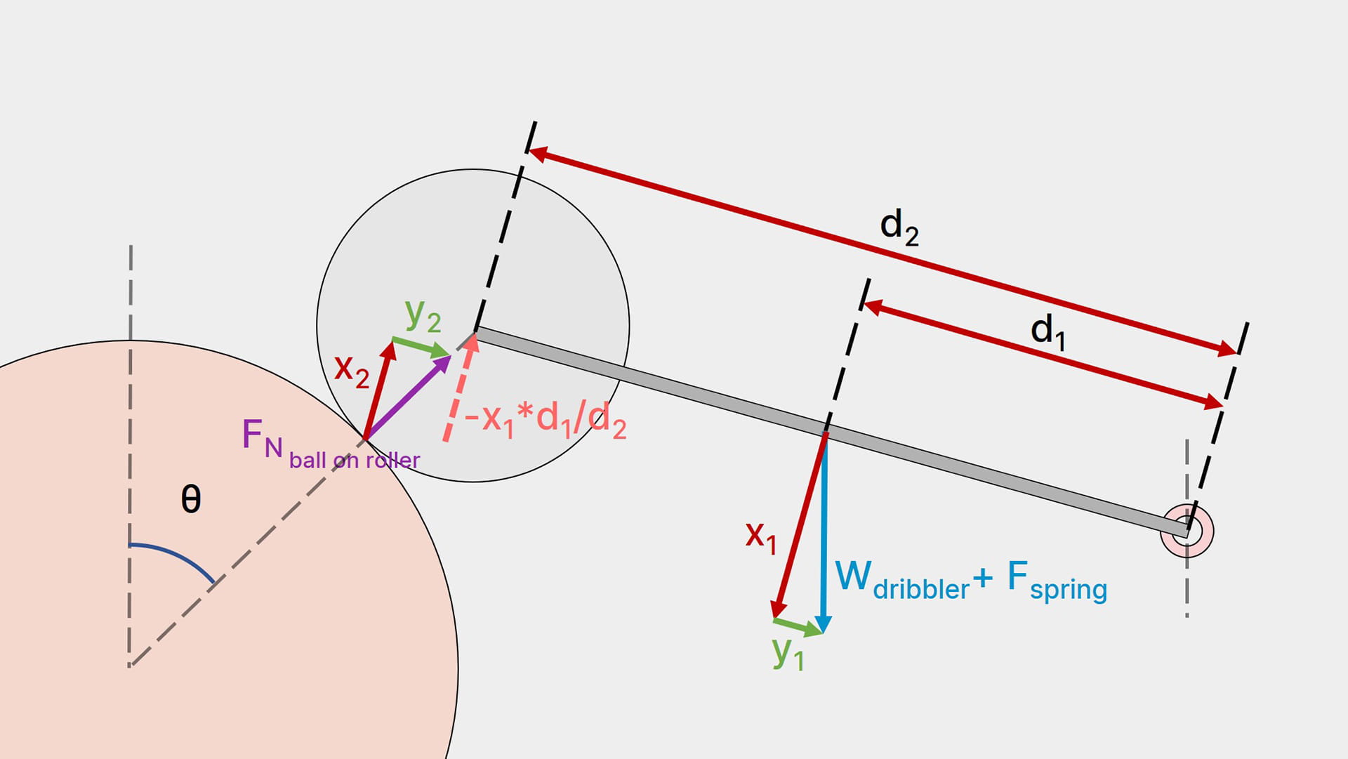
The height of the pivot point’s position determines how well the dribbler can absorb impacts
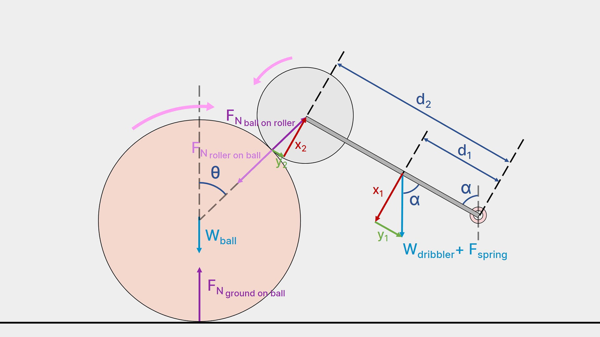
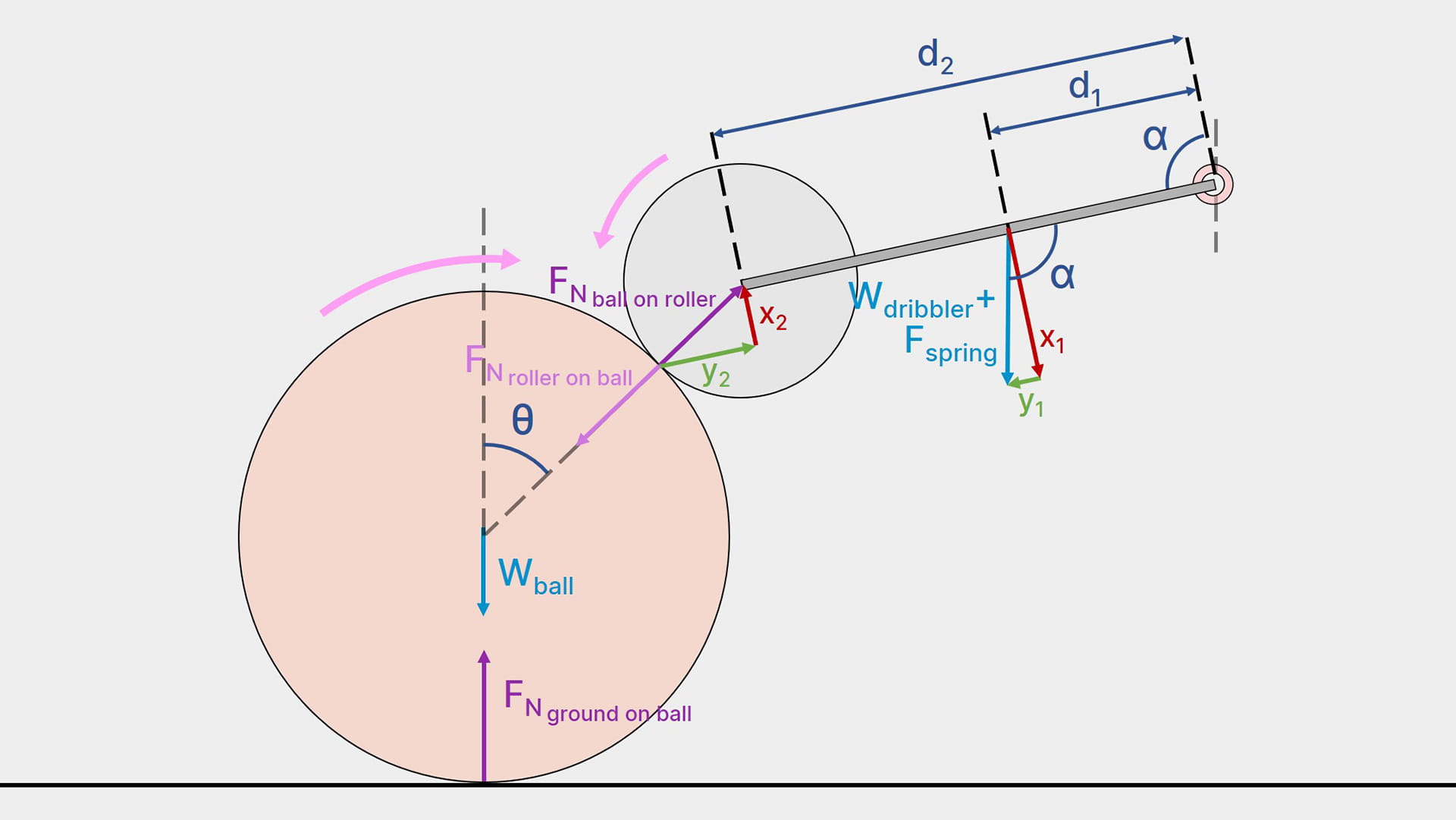
The higher the pivot point, the harder it is for the incoming ball to lift the dribbler up. This is because the component that is perpendicular to the lever, the red arrow, x2, becomes smaller.
Also, the dribbler becomes less capable of absorbing the ball’s impact since a larger proportion of FN:ball on roller is directed along the length of the dribbler (green arrow, y2), which is rigid, and would produce an equal and opposite reaction force that pushes the ball outwards.
Notice that when α is larger than 90 degrees, Wdribbler + Fspring produces a component parallel to the lever, y1, that is in the opposite direction of y2, further preventing the ball’s impact from being absorbed.
Factor 2: The higher the pivot point, the harder it is to tilt the dribbler and the worse it is at absorbing impacts.
Pivot Distance
The distance from the roller to the pivot point changes how much force is needed to lift the dribbler, assuming changing the pivot point does not move the dribbler’s centre of gravity.
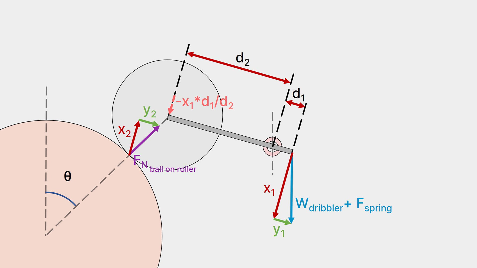
In the diagram, the dotted red arrow (-x1d1/d2) represents the force that is needed to keep the dribbler in rotational equilibrium (it is not an actual present force).
When the pivot point is located in front of the CG, the dribbler will have the tendency to tilt backwards. Hence, the force needed to keep the dribbler from rotating clockwise is in the opposite direction of the normal force from the ball to the roller, which means the dribbler cannot keep contact with the ball. This is why the pivot point must not be in front of the CG.
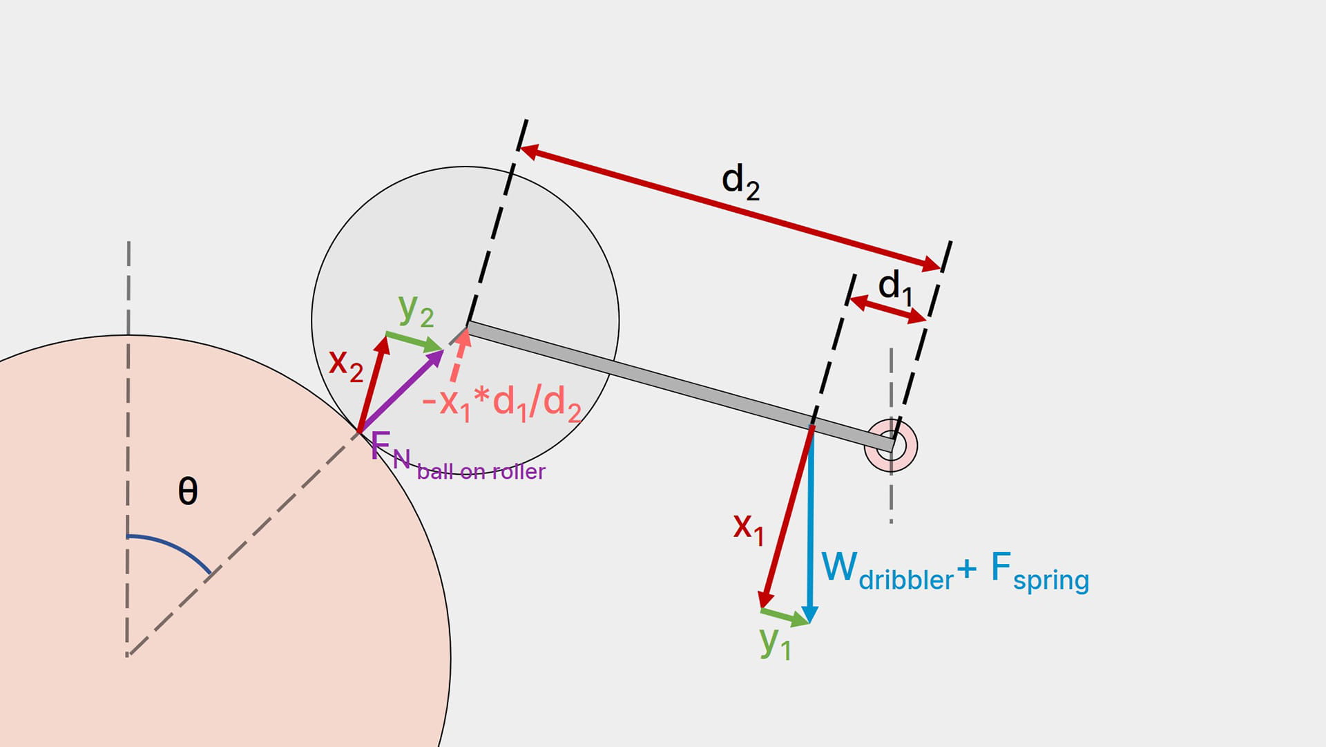
When the pivot point is located behind the CG, the further it is, the larger the force required to lift the dribbler since the force needed is a directly related to d1/d2.
Another effect of this is that the dribbler’s tilting trajectory will be more “upwards” than “backwards” since the circular path it follows is larger.
Factor 3: The pivot point should be behind the CG, and the further back it is, the harder it is to tilt the dribbler, but the stronger the adhesion between rollers and the ball. The dribbler’s trajectory will also follow a more vertical path.
Spring Strength/Position
This should be quite intuitive. Regardless whether the spring is pushing the dribbler down, i.e. it becomes compressed when the dribbler is lifted, or if the spring is pulling the dribbler down, i.e. it becomes stretched when the dribbler is lifted, a stiffer spring will produce a stronger force downwards.
The nature of a spring is such that it provides an increasing downwards force the more it is distorted (i.e. the more the ball pushes into the dribbler module), thus ensuring that the rollers maintain contact with the ball.
Fspring is assumed to be positioned at the CG and in the same angle as Wdribbler in the free body diagram for easier calculations. However, this is often not the case The positioning of the spring should also be intuitive.
- The closer the spring angle is to being perpendicular to the lever, the greater its effect on exerting its restoring force.
- The closer the spring’s position is to the pivot point, the smaller the effect of its restoring force, since the anti-clockwise moment created about the pivot is smaller.
- The spring length should not be so short that it has to be stretched a lot even from the dribbler’s resting position, but not so long that it becomes loose and provides no downwards force at rest.
Factor 4: The stiffer the spring, the harder it is to tilt the dribbler, but the stronger the adhesion between rollers and the ball when the ball is in a stable dribbling state.
Ideal Dribbler
Based on the 4 key factors above, here is the design process for an ideal dribbler.
- Set the roller position to be as high as possible to maximise the friction of the ground on the ball, increasing hold on the ball. However, they cannot be too high or the rollers might not have sufficient friction to spin the ball. A good rule of thumb is to keep θ just below 45 degrees.
- Place/Construct the remaining components around the roller’s position.
- Find a suitable height for the pivot point; this should be as low as possible.
- Place the pivot point just slightly behind the centre of gravity (at the height determined in the previous step).
- Place a spring of appropriate length such that it is mildly stretched/compressed when the dribbler is at rest, so that it provides a small constant downwards force on the dribbler, keeping it level.
- Tune the spring strength until it is strong enough that it can push/pull the dribbler down to keep the rollers in contact with the ball at all times, but weak enough that the ball can fully enter the catchment area when the dribbler is in dynamic equalibrium.
Imagine a state where the dribbler is dribbling the ball in a state of dynamic equilibrium, where
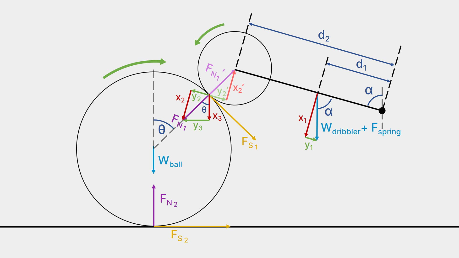
- Wdribbler + Fspring is the combined downwards force of the dribbler's weight and restoring force of the spring, acting from the dribbler's centre of gravity.
- Fspring is assumed to be perpendicular to the ground and acting from the centre of gravity for ease of calculation.
- x1, y1 are components of Wdribbler + Fspring that are perpendicular and parallel to the lever.
- FN1 is the normal contact force acting from the roller onto the ball.
- x2, y2 are components of FN1 that are perpendicular and parallel to the lever.
- x3, y3 are components of FN1 that are perpendicular and parallel to the ground.
- FN1' is the normal contact force acting from the ball onto the roller. It has the same magnitude as FN1 but directly opposite in direction.
- FS1 is the tractive force acting on the ball from the roller.
- Wball is the weight of the ball.
- FN2 the normal contact force acting from the ground onto the ball.
- FS2 is the frictional force acting on the ball from the ground.
Assume the dribbler is dribbling the ball in a state of dynamic equilibrium, the clockwise moments will equal the anti-clockwise moments about the pivot.
Hence, supposing that θ and α are acute angles, they should both sum up to as close to 90 degrees as possible in order to maximise the normal contact force between the ball and rollers.
This can be done by modifying the roller position (changes θ) or the pivot height (changes α).
where μ1 is the rolling friction coefficient between the roller and ball (if the ball was stationary this would be the static friction coefficient).
To maximise this coefficient, the roller needs to be rough and possibly slightly sticky to increase adhesion.
It is clear that as θ decreases, cos θ approaches 1. Therefore, the higher up the ball the rollers are, the larger the normal force between the ground and ball, and the larger the friction between the ground and ball.
Also, μ2 is the coefficient of sliding friction between the ground and ball (similar to μ1, if the ball was stationary this would be the static friction coefficient instead). This should remain largely constant throughout the match.
For the ball to start spinning, the clockwise moment about the ball's centre, created by the rollers, must be larger than the anti-clockwise moment, created by the ground friction.
Evidently, as θ decreases, the anti-clockwise moment (R.H.S.) increases significantly. If the anti-clockwise moment becomes greater than the clockwise moment, then the ball will end up jammed into the dribbler without spinning, with the rollers slipping on the ball.
In addition, the spring is used to absorb impacts. Assuming the spring used is a linear rate spring, Hooke's Law applies,
where Fspring is the restoring force, k is the spring constant, and x is the displacement of the spring after it is stretched/compressed. This means that Fspring is directly proportional to k and x.
Hence, as the stiffness of the spring (value of k) increases , the magnitude of Fspring increases linearly.
Also, as the dribbler is tilted further(as the value of x increases), caused by the ball's backwards force into the catchment area, the magnitude of Fspring increases linearly, opposing the force of the incoming ball and reducing its acceleration.
Powertrain
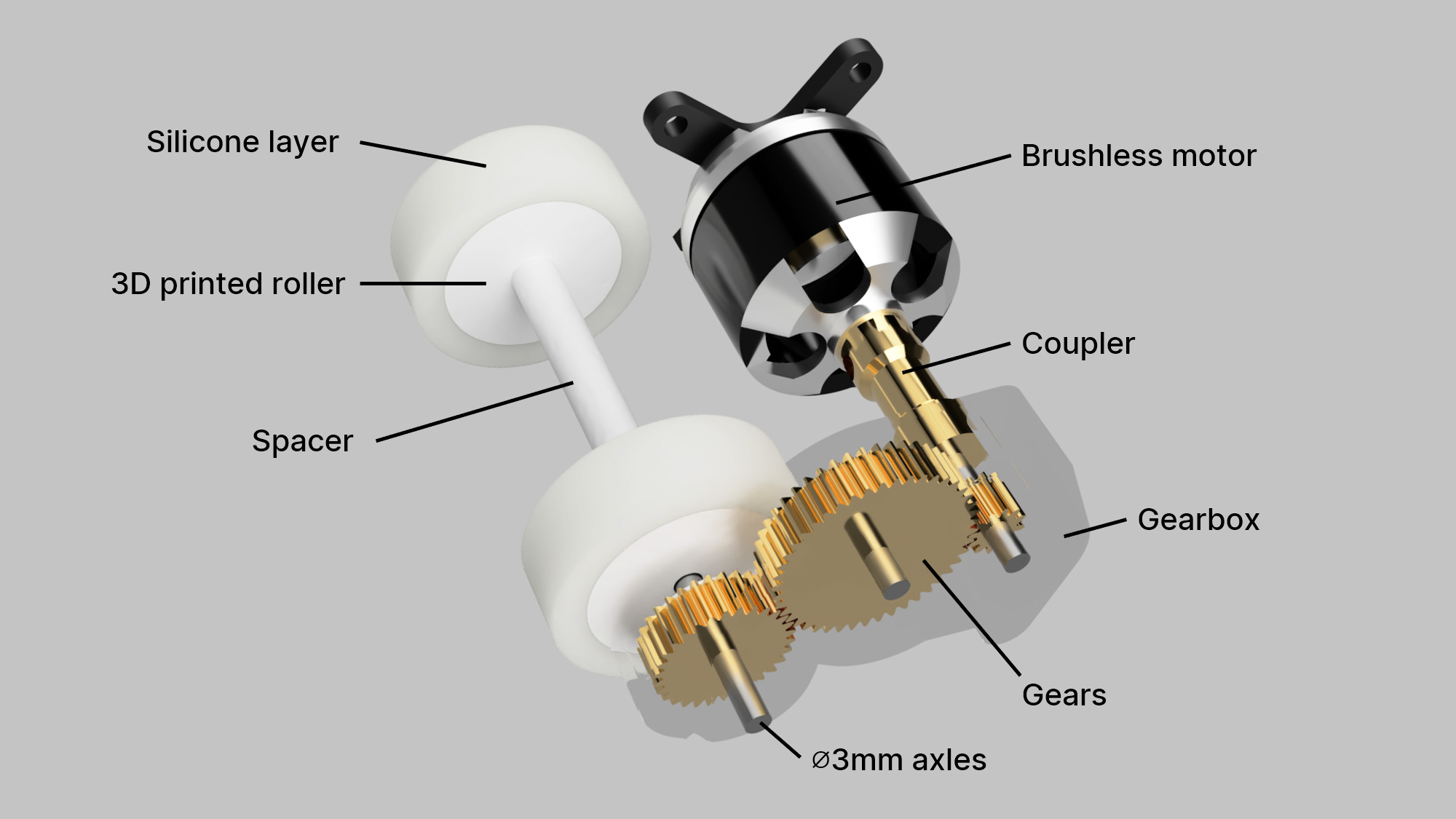
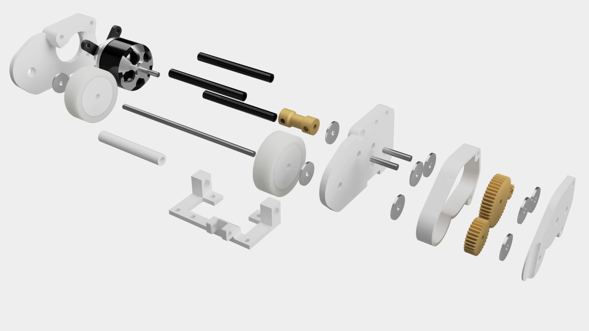
Here is a breakdown of every component that drives our dribbler.
Motor
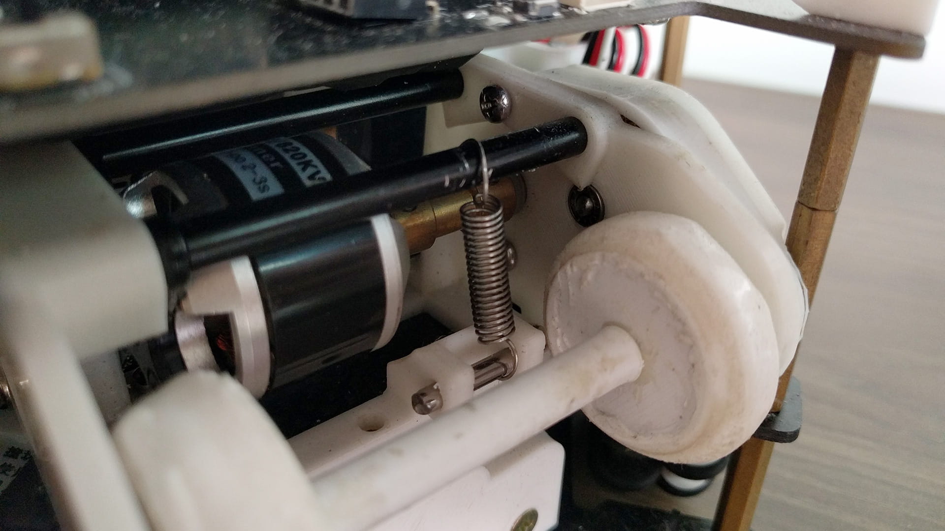
The motor we used is a 820 kV (RPM per volt) brushless motor. With a battery at 12V, this gives our dribbler system an input speed of around 9840 RPM.
The motor also has one of its 4 legs on the cross shaped mount sawed off to prevent it from hitting the roller in front.
Coupler
A 3mm to 3mm coupler is attached to the motor’s axle. The motor cannot drive the gear directly because of two reasons: one, the motor shaft is only 10 mm long so it is too short to hold the gear, and two, the gear was directly epoxied to the axle and sensibly, we definitely did not want to glue the gear to the motor directly.
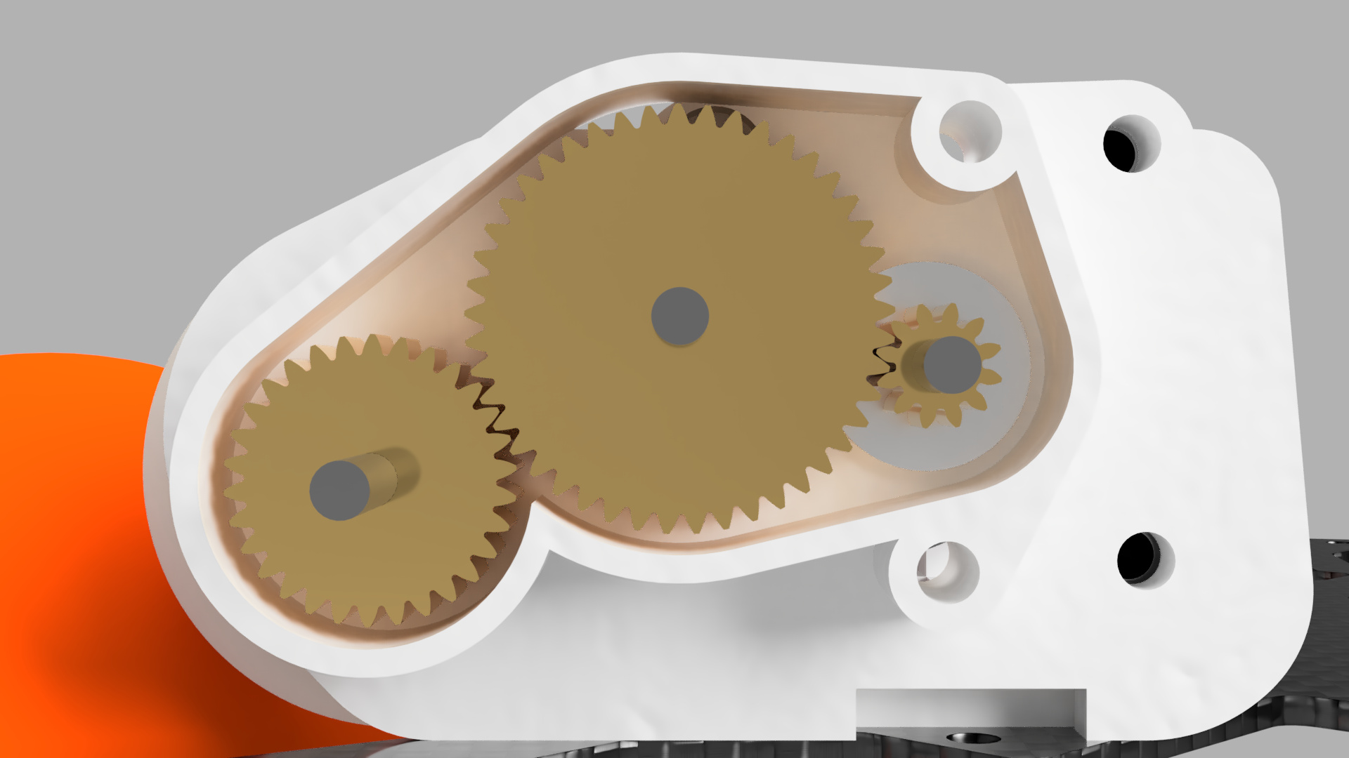
Gears
The gear train has a ratio of 12:45:30. This means (assuming 100% efficiency for ease of calculation), the output speed is at 3936 RPM. We made it geared down since the brushless motor was quite low torque and we wanted to ensure the dribbler was strong enough to not stall out.
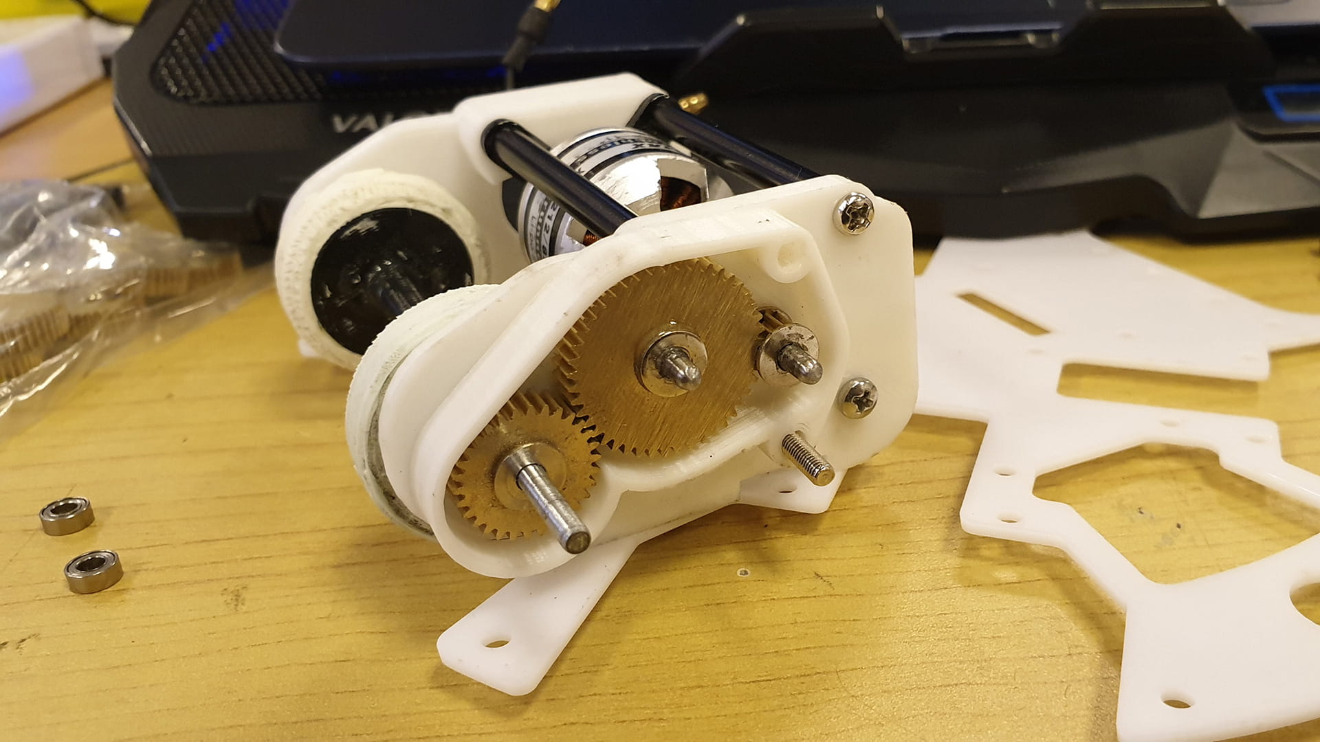
These are all 5mm thick gears machined out of copper and are sold with pre-specified dimensions. (12 tooth gear, 20-39 tooth gear, 40-59 tooth gear). These gears have a hole of 3mm diameter and are securely glued onto a 3mm steel axle using Araldite epoxy.
When designing the gear placements, we took the larger radius (tip of gear tooth to centre) to represent the middle gear, while taking the smaller radius (base of gear tooth to centre) to represent the other 2 gears. This gave a half teeth spacing between the gears, which gave just enough leeway for the gears to spin freely while being close enough to not experience gear slippage.
Rollers
For the rollers that dribble the actual ball itself, we used 2 separate rollers instead of a single cylindrical bar. An obvious benefit of this would be a better hold of the ball since it is centralised and trapped in place in the catchment area.
Separate rollers also spin the ball faster. This is because rollers contact the sides of the ball whereas a bar contacts the middle of the ball. If we draw a line along where the ball is contacted (black line in the figures below), it creates a spherical cap and it is clear that the radius of the spherical caps created with the separate rollers is smaller than the radius of the spherical cap created with the bar (which is essentially the radius of the ball itself).
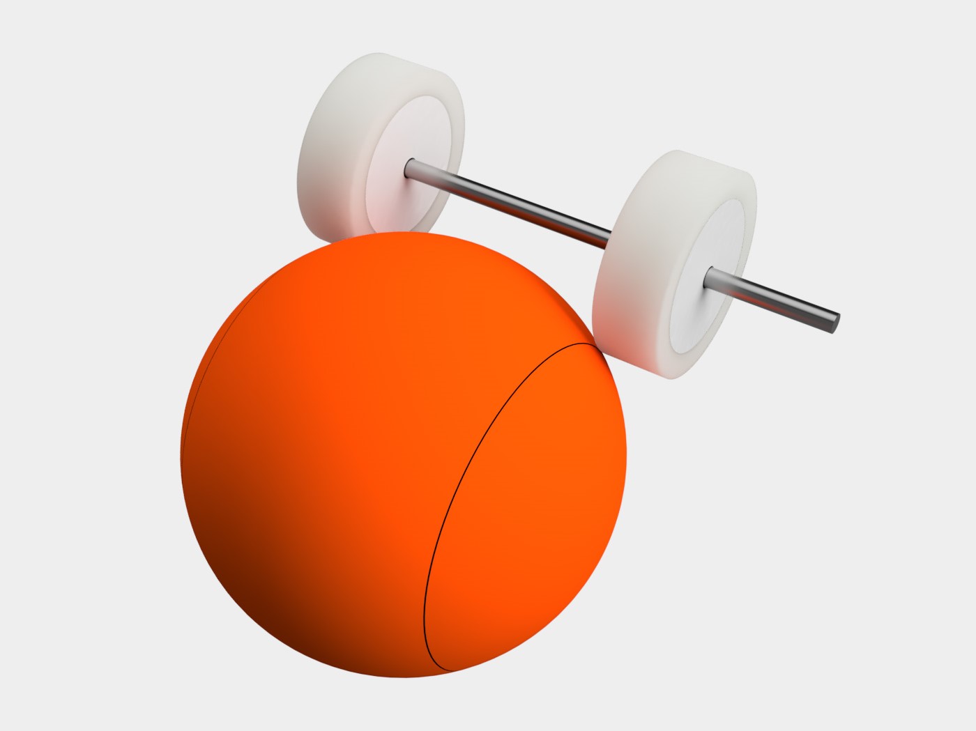
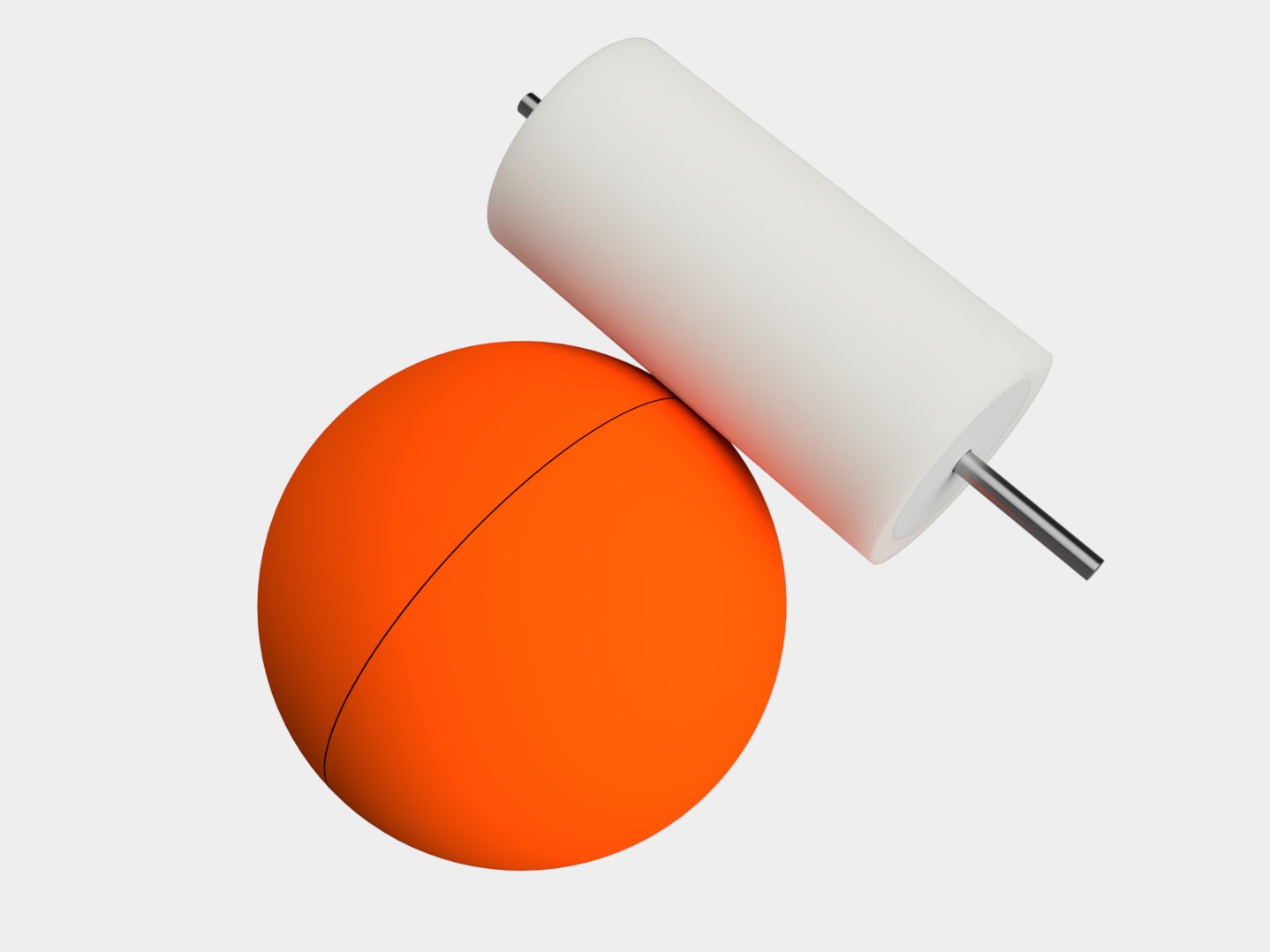
Thus, given the same speed, the separate rollers can spin the ball faster than a bar since the speed transfer ratio between the roller and the ball is simply the radius of the roller to the radius of the circle along the point of contact. This is also why the rollers were made to be as big as possible.
Estimates using a Spherical Cap calculator places the roller to ball ratio at about 15.5:25, which puts the maximum ball spinning speed at above 2000 RPM. This video of us measuring the ball’s RPM with a laser tachometer proves this calculation to be true.
Each roller is made by coating a layer of silicone around it for more friction between the roller and ball. We have experimented with a few types of silicone and different brands, and found Araldite silicone sealant to be the best in terms of grip and durability. The silicone is coated by mounting a 3D printed roller into a special mount that leaves a roughly 5 mm gap between it and a chamfered edge. The silicone is fed into the chamfered edge while the roller is spun slowly with a drill. Once a relatively clean layer of silicone is created, it is left to dry for about a day before being removed and epoxied onto the dribbler axle.
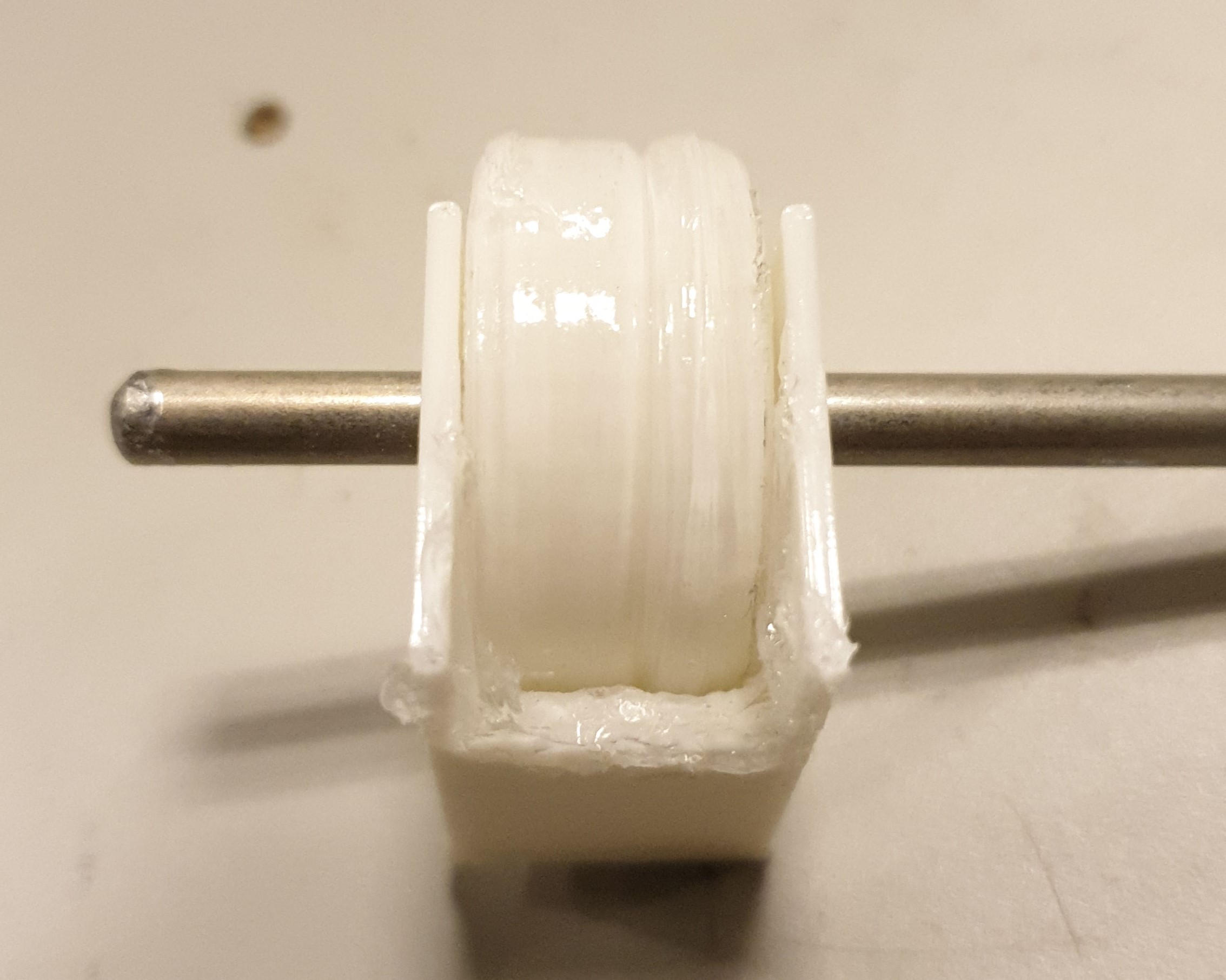
The disadvantage of separate rollers is if one roller has a better grip on the ball, it might generate unwanted sidespin on top of the ball’s backspin. To prevent this, a spacer is placed in between the rollers to keep them a fixed distance apart and it is epoxied to both rollers, ensuring they spin as a single body. The rollers are also typically coated in silicone in pairs to keep them as identical as possible.
Suspension
A suspension system for the dribbler is necessary for it to absorb large impacts and increase its stability while dribbling. If a dribbler is rigidly connected to the robot, all impacts are fully absorbed by the robot itself, which can cause problems such as the front wheels being lifted up, as shown in the video below.
The robot absorbs the full impact of the ball
Besides, in a real match, the robot and ball are always in a dynamic (moving) state. Thus, a suspension system can compensate for the varied range of forces acting on the ball in order to maintain full control over it.
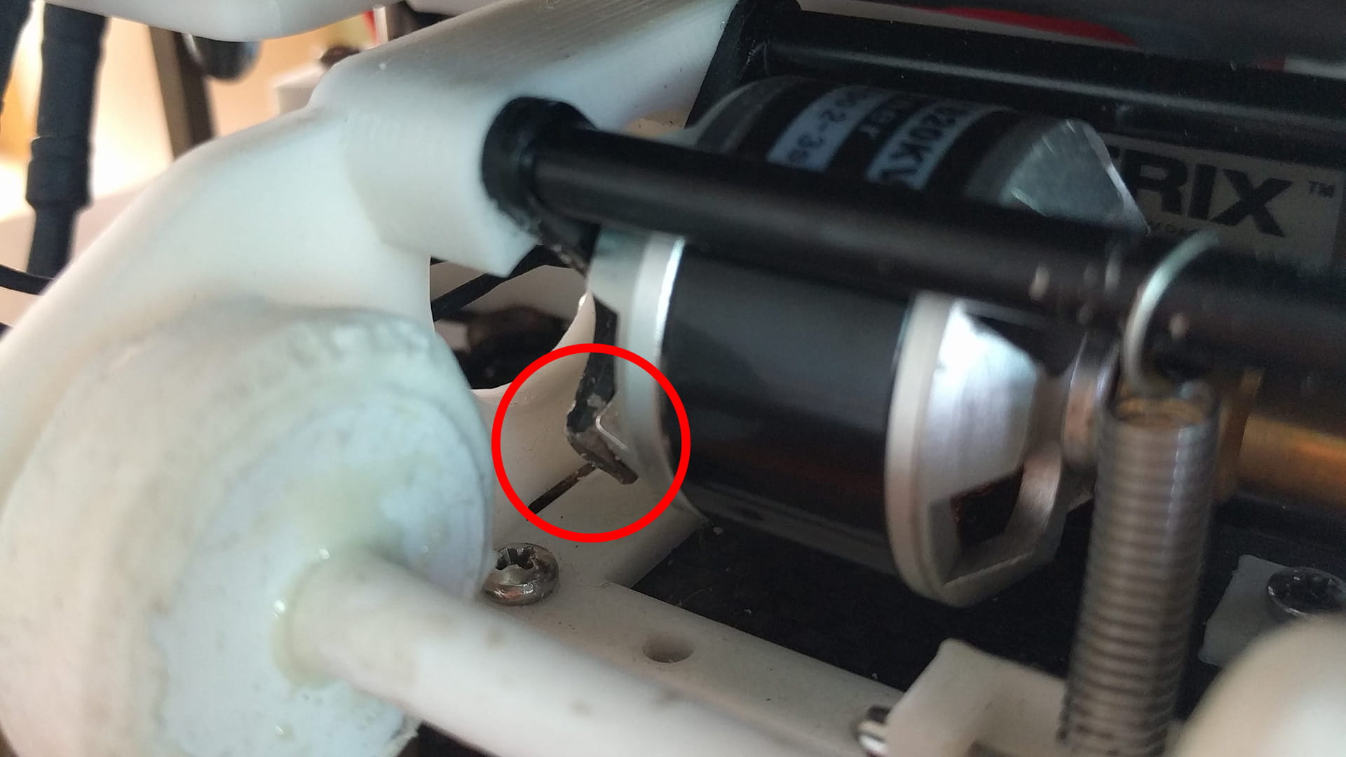
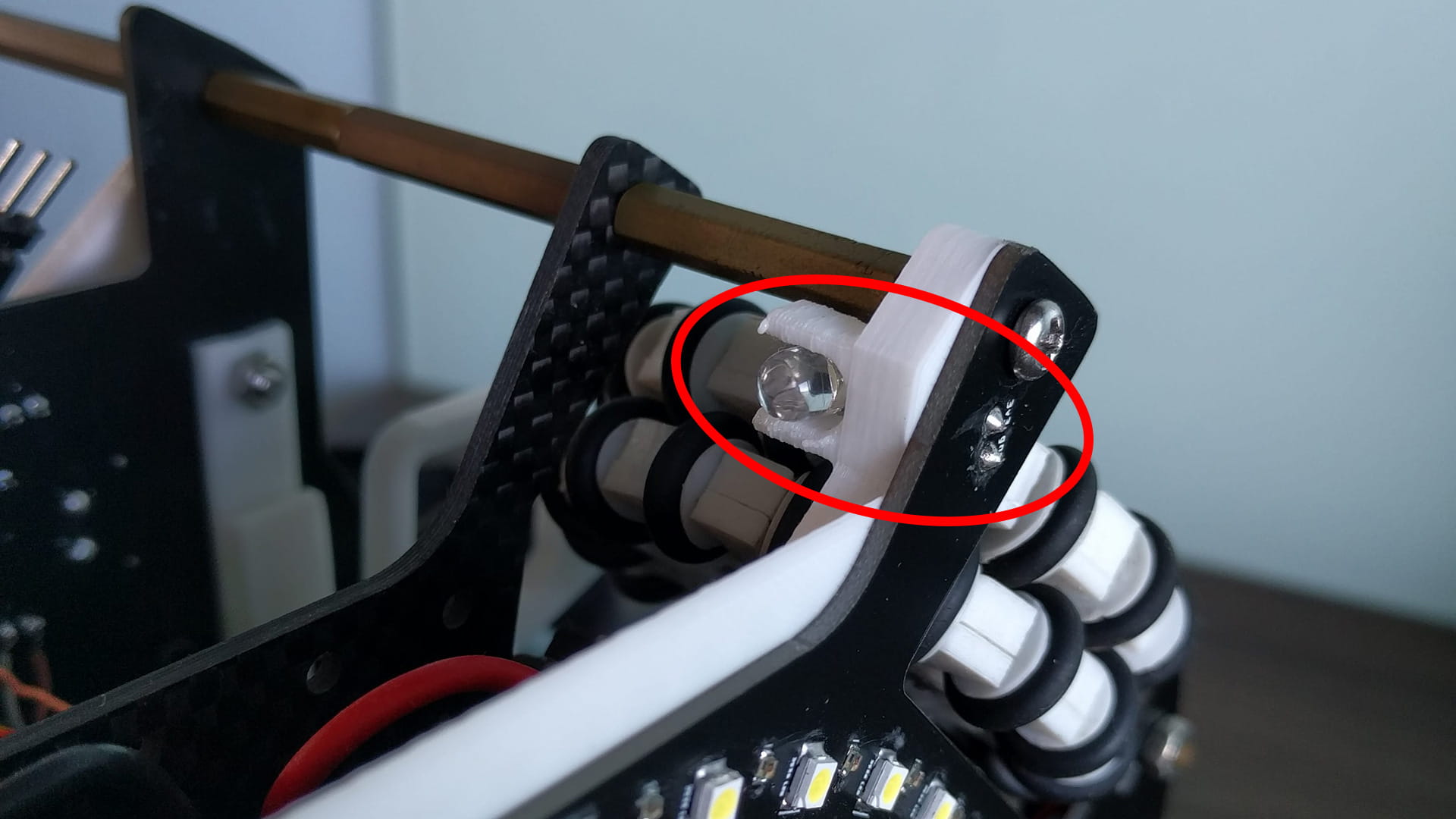
Pivot
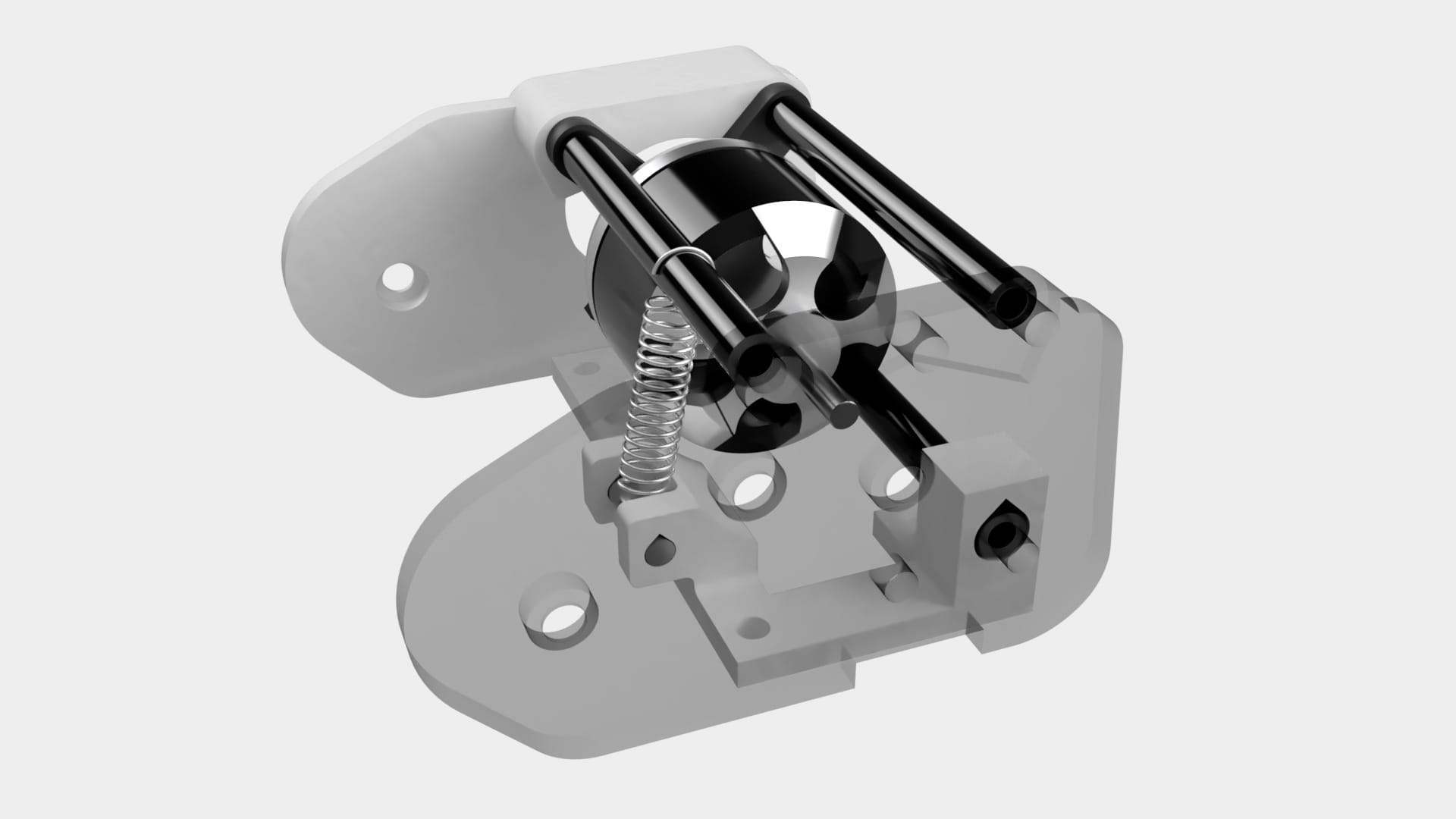
Following the theory on the pivot point, we wanted the dribbler to pivot about a point that was low to better absorb impacts, and just slightly behind the centre of gravity to reduce the amount of downwards force on the ball, since the amount of downwards force can be tuned with the spring strength later.
For design convenience, we simply chose the bottom inner leg of the motor mount as the pivot point. Thus, the circular aluminium rods used to secure the motor in place doubled up as axles for the dribbler’s fulcrum. A slightly oversized hole held these aluminium rods in place, leaving just enough tolerance that the dribbler can pivot smoothly but not too much that it starts wiggling about.
This pivot point was quite suitable since it was only slightly behind the centre of gravity. However, our final pivot position could be lowered more to allow for better shock absorption (AFI).
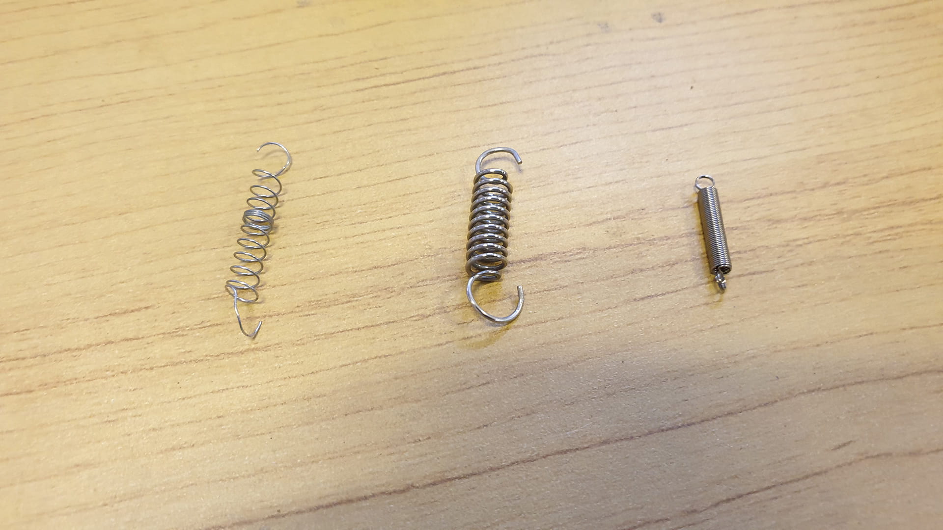
Spring
A spring is needed to absorb the impact of a ball (by converting the ball’s kinetic energy to elastic potential energy in the spring). It also produces a downwards force that keeps the dribbler pressed against the ball.
Without a spring, the initial impact of a fast moving ball travelling towards the dribbler or the acceleration of the ball into the catchment area by the dribbler’s rollers itself can produce a huge amount of force upwards. This causes the dribbler module to “jump” upwards, then come back downwards with the full force of the dribbler’s weight, which pushes the ball back out.
The first video is of our current robot’s dribbler, but without its spring, and it shows the dribbler module bouncing up and down uncontrollably.
This second video is of an older robot. The backwards acceleration of the ball caused by the dribbler results in it hitting the circular bar located below the ball with a large force. This produces an upwards force on the ball, causing it to “jump” while rebounding off the back wall.
There are 2 ways for placing a coil spring for our dribbler, either it is compressed when lifted or stretched when lifted; both methods work equally well. We chose to use the second method simply because it was easier to design for that in our case. The spring has one end that is hooked onto a stationary bar on the base plate (2nd layer), and another end that is hooked to the upper circular aluminium rod of the dribbler module.
As with the ideal dribbler theory above, the spring length is chosen such that it is slightly stretched when the dribbler is in the resting position, so that it can stay hooked on the dribbler while providing some initial downwards force to keep the dribbler stable.
Another factor for consideration is the strength of the spring; it cannot be too stiff nor too soft. An overly stiff spring will result in the dribbler being unable to pivot up when it is dribbling at equilibrium, which means the ball is not fully within the catchment area. On the other hand, an overly soft spring will allow the dribbler to pivot with little resistance, as if the spring isn’t there in the first place (see theory for spring strength).
Experimentation with spring stiffness was done with the couple of different sized coil springs we had lying around our lab. We tried with a few random pen springs (all too short, had to be pulled beyond yield point to fit the length needed), a spring with a 0.8mm section thickness (too stiff), and a spring with 0.3mm section thickness (too soft). After some estimation, we bought another type of spring (~0.5mm section thickness) which was about an average between the stiff and soft spring. Surprisingly it worked pretty well!
Damper
Typically, with a suspension system (e.g. car suspension), a damper is added to absorb the recoil of the spring. However, we did not add a damper to our dribbler because:
- It was very difficult to find a damper that was both suitably small and weak for our use
- It would further complicate the design, especially considering our smaller size constraints
- The spring we used was rather soft, so the recoil force was small enough for it to not affect the system too much.
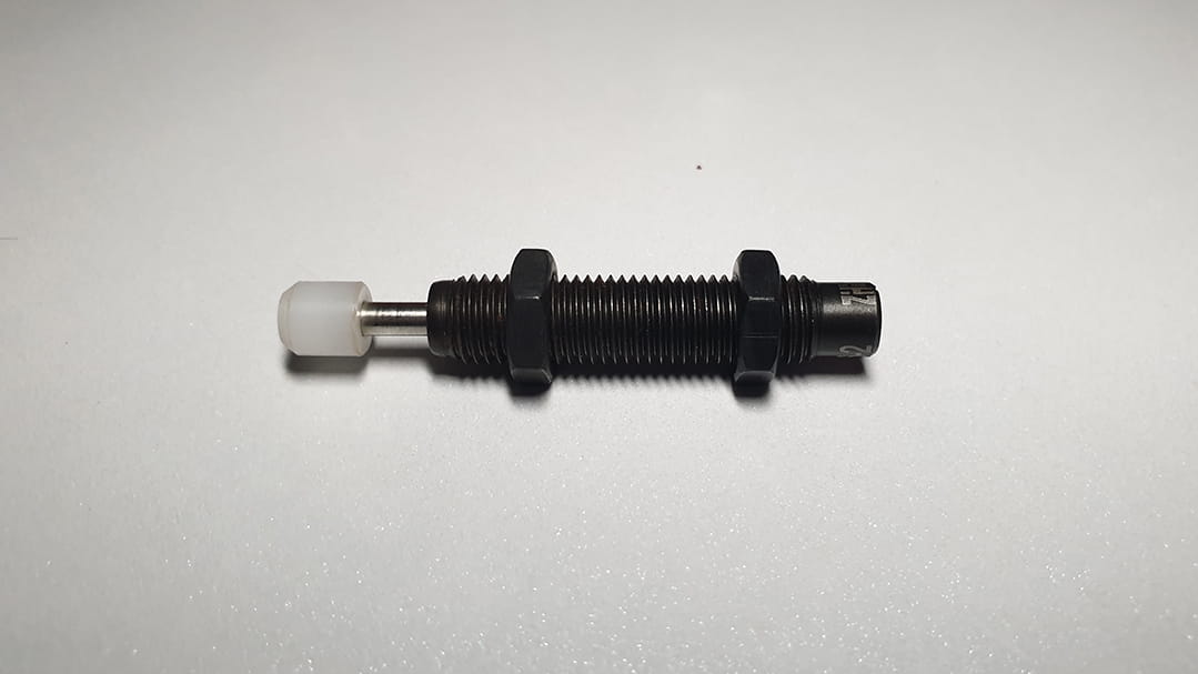
We may still investigate the possibility of using a damper in our design, especially since many of our inspirations stated above do use an oil damper in their suspension system, while slow motion footage of our dribbler still shows a small amount of oscillations when the robot is moving with the ball, which could be eradicated if we found (or made 🤔) a suitable damper. However, the dribbler already works very well as it is now, so redesigning it to fit the awkwardly shaped damper will likely not happen anytime soon.
Structure
A well-designed structure is required to hold all the dribbler’s components together. Here’s a breakdown of the small parts that actually make up the dribbler.
Ramp
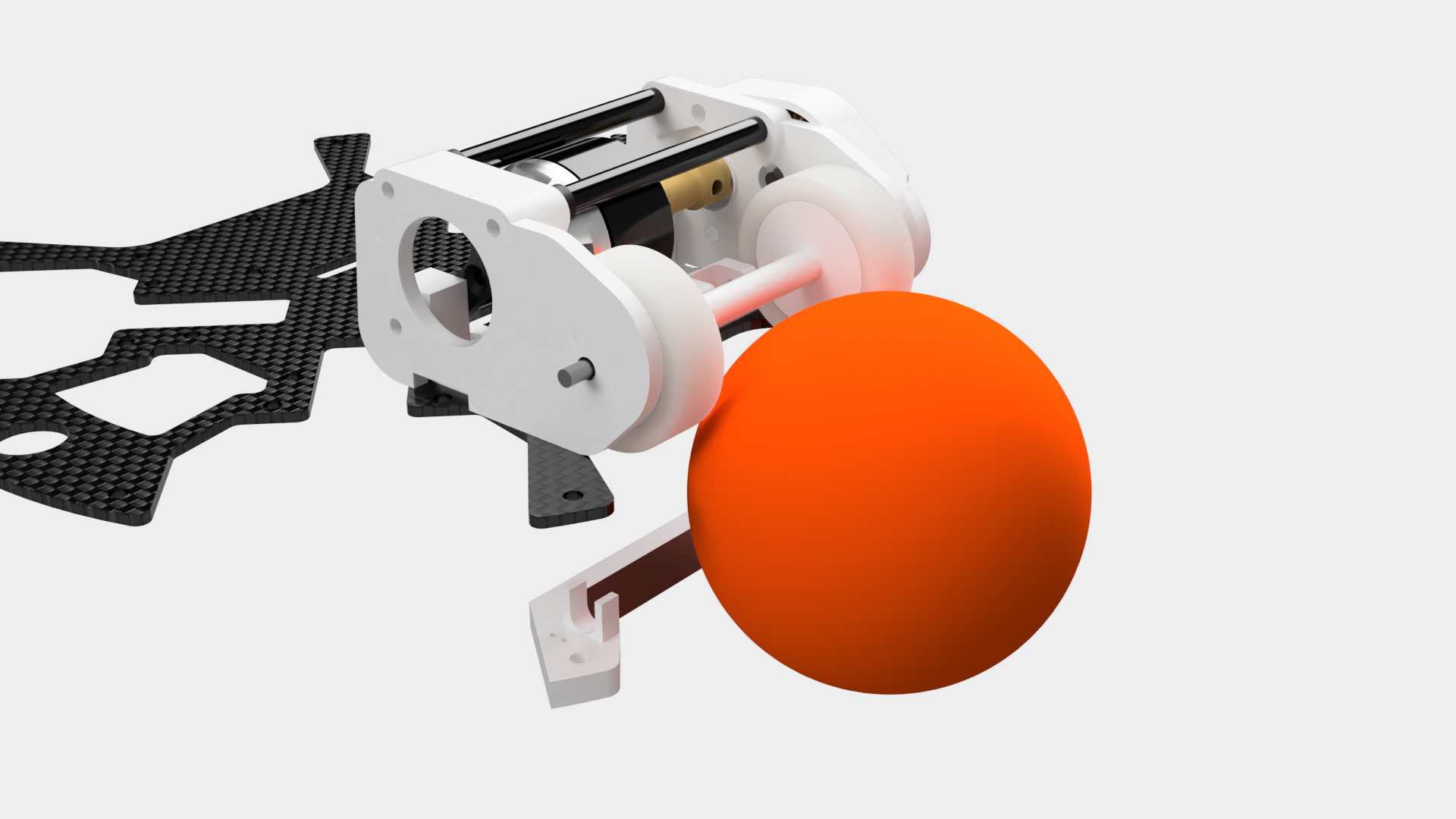
The ramp is not an actual part of the main dribbler module, but is one of the most important parts that improved our dribbler’s performance significantly. This is simply a 3D printed piece that provides a 45 degree plane near the bottom of the ball.
Previously without the ramp, the ball would move backwards and strike the back plate with a considerable amount of force. By Newton’s Third Law, the back plate produces an equal and opposite reaction force that pushes the ball out of the dribbler. This results in a “bouncing” or “repelling” effect, as presented in the video below.
Adding the ramp fixed this problem since it redirected most of the backwards force upwards. This not only stopped the ball from bouncing out of the dribbler, but it also improved the dribbler’s performance since most of the backwards force of the ball was used to push itself up into the roller, which increased its grip on the ball.
This piece also doubles up as a light gate with holders for the LED and LDR as well as tiny holes for the legs to fit through and be soldered directly to the PCB’s through hole pads located underneath. (In hindsight, this isn’t that great of an idea since the 3D printed piece has to be semi-permanently stuck to the PCB unless the LED and LDR are desoldered… possible AFI here)
Bearings
Due to the extremely high rotation speeds of the dribblers’ gears, all axles are mounted in bearings to ensure they can spin properly. (MR63ZZ 3*6*2.5mm bearings)
On the dribbler plates, the bearings are embedded one-way such that they dont fall out on the other end. Most bearings are placed on the inside, facing the gears so no matter how jittery the motion gets the bearing will never fall out.
Spacers
It might seem weird why we would consider spacers to be a vital part of the design, but there’s good reason, mainly from our history of experimenting with dribblers. With the extremely high speeds of the gears, if the gear was be in contact with any of the plates, the friction generated would actually melt the plate itself. The picture below was that of an older dribbler plate that used acrylic gears. The sheer heat generated from the spinning gear melted the plate and now they are fused together and impossible to remove.
Thus, a 0.7 mm spacer was added to each side of the gear, on top of an additional 1mm gap between the dribbler plates, to prevent such a cursed event from hapenning again (and it has worked pretty well so far).
History
The process of making our dribbler (TO BE UPDATED)
Lego dribbler, acrylic gears, roller experimentation (lego wheels, bar, curve roller, conic mirror, straight roller), motor (brushless motor speeds, maxon motor)