Assorted Parts
This section lists out all the remaining components that are too small/unimportant to get an entire section for itself 🙃
Battery Holder
The battery is usually the single heaviest part of the robot (our battery weighs over 300g), thus a sturdy holder for the battery is necessary to prevent it from shifting about and potentially affecting the robot’s movement.
Our battery slot is made up of two layers of 3 3D printed pieces that form the outline of a cuboid compartment for the battery. The front 2 pieces form a chamfered opening that allows for easy placement. The width of the opeining of the battery slot was designed to be just about the actual width of the battery. Hence, the battery slot itself is already a “clamp” that holds the battery firmly in place and does not allow it to move about.
The cover to prevent the battery from falling out is a spring-loaded up-down gate that makes it very easy to insert and remove the battery.
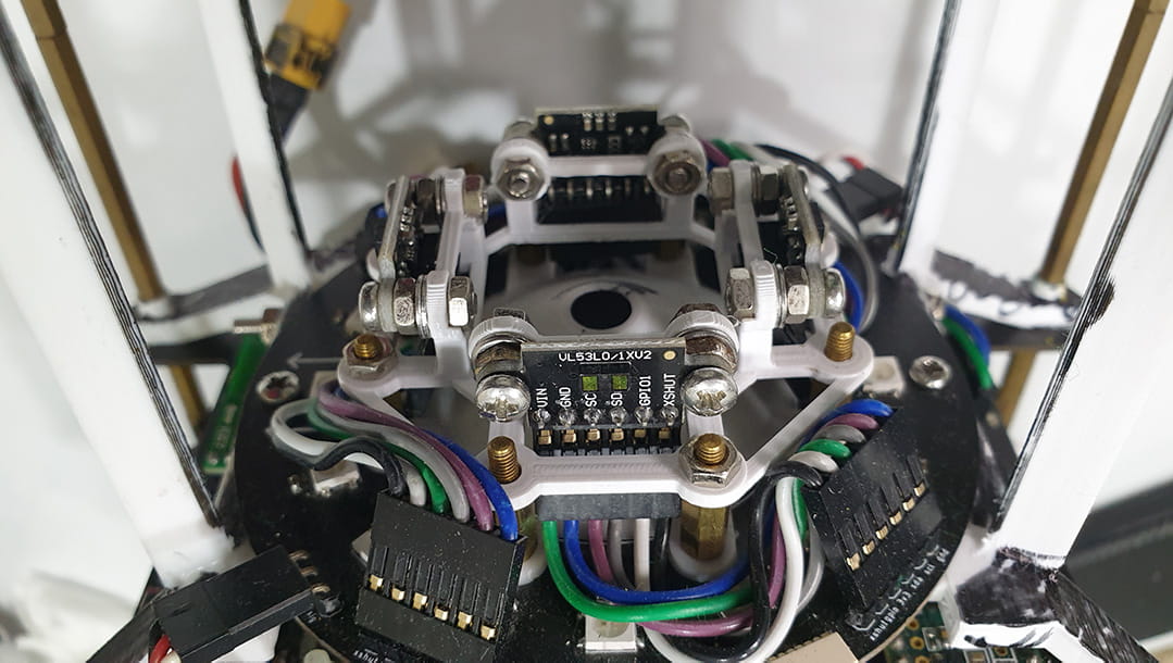
TOF holder
Our TOF holder is a 3D printed frame, allowing the TOFs to be screwed into place.
Handle
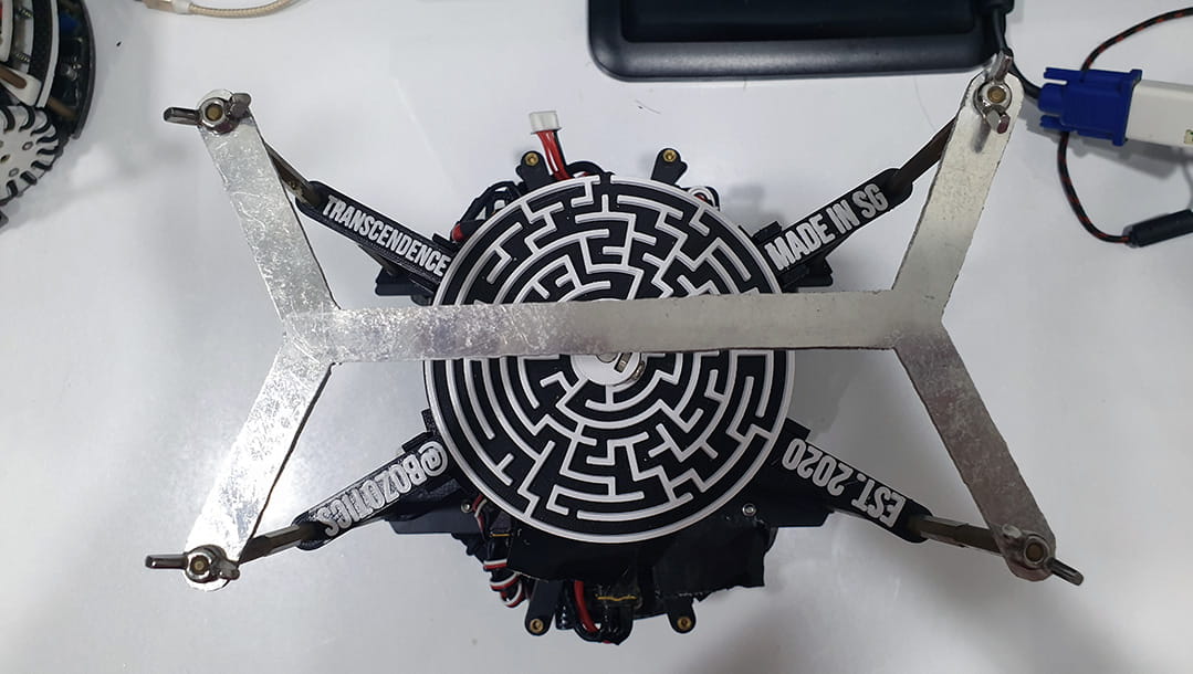
The handle is sawed out from a 2 mm alumininum metal plate and is mounted on the 4 main supporting stands of the robot. The reason we opted for aluminium, other than its strength, is because of tradition: a callback to our past where we used manually sawed metal plates for our robot’s layers… 😂 The handle is also supported by 4 points, as continued from the bottom layers, which adds to its stability and strength.
Main switch
Our main switch is a missile switch. Why? Because its cool. Yep, that’s it.
Microprocessor placements
As simple as it may seem, the position and orientation of the microprocessors used is extremely important to ensure ease of programming.
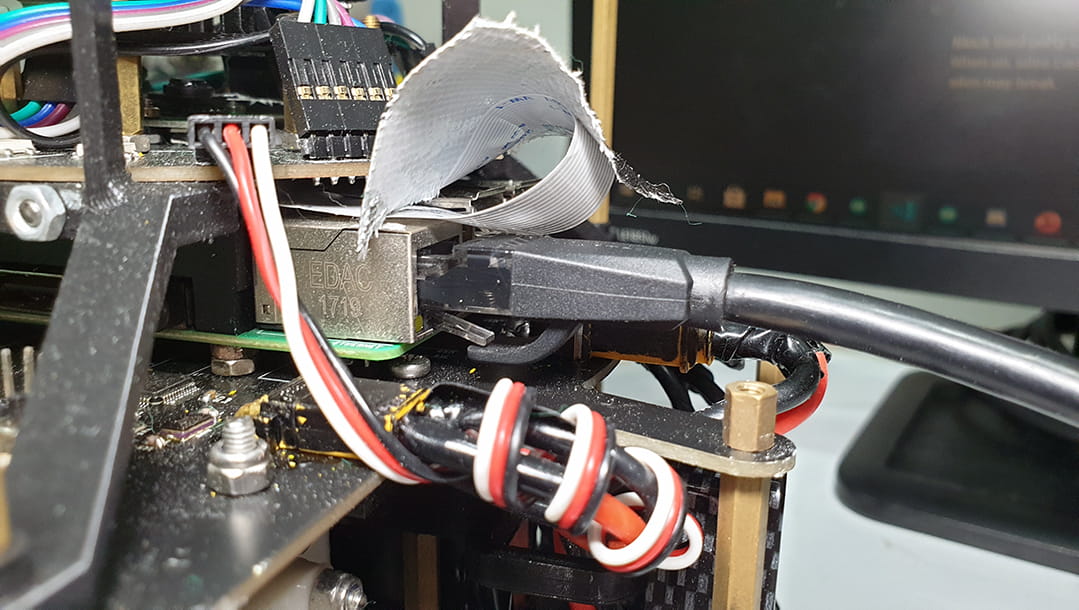
The Raspberry Pi is placed directly under the Layer 4 PCB, where the Raspberry Pi camera is mounted, such that the wire goes up to the camera directly. More importantly, the Pi is elevated by around 5mm, which allows the ethernet cable to be easily unclipped and extracted.
The Teensy 3.6 is located adjacent to the Raspberry Pi, with its micro-USB port facing the same way as the Pi’s ethernet port. There is also a small indent designed into the trapezium mount above the Teensy, allowing for the program mode button to be pressed easily.
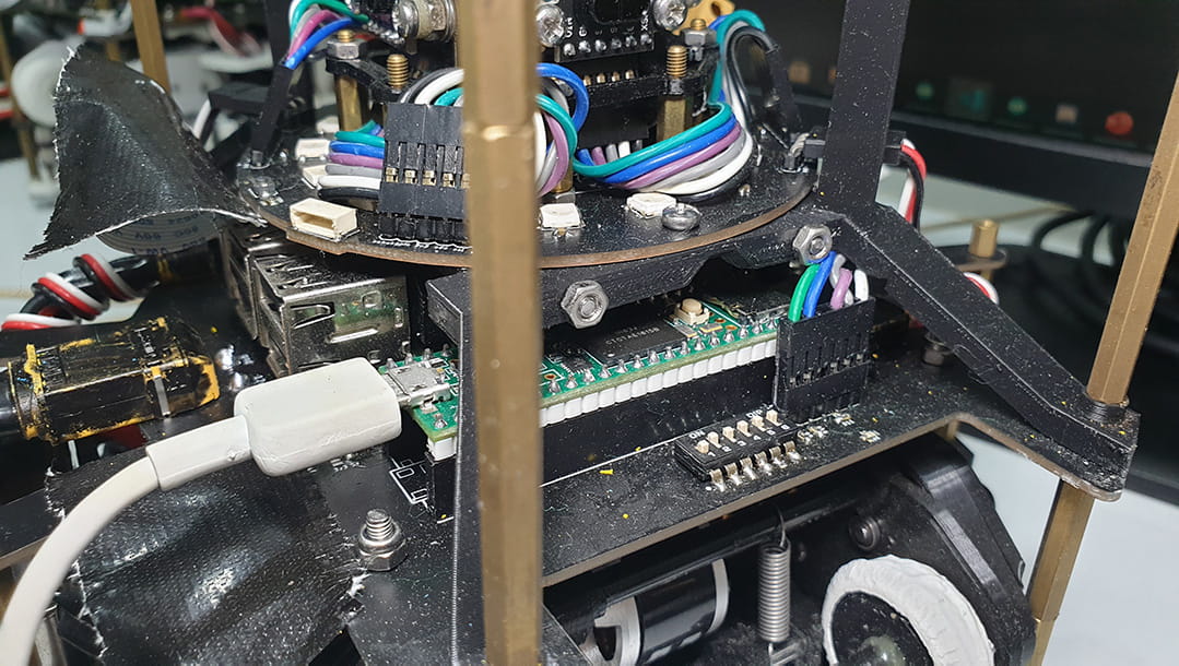
The SH1.0 connectors (used for programming the STM32 chip through SWD) can be easily connected to on each layer. The reset button and indicator LEDs are also located close by and are equally accessible.