Rescue Line - March Update
A long time has passed since the last Rescue Line update as I’ve been mostly working on getting the Soccer robot up and running, but since everyone is waiting on parts to arrive from China it’s time for another update!
I tried to make this blog as comprehensive as possible, but if there is anything you would like to know more about or anything that is confusing, do feel free to reach out to us!
Base upgrades
Previously, our drive base was a monolithic 3d printed part which was heavy, wasted a lot of filament and took a long time to print. This made our base very inflexible and chunky, which was not desirable since at that point, we haven’t designed our claw and ball collection mechanism, thus it made it difficult to integrate into the old base.
Since then, we have redesigned our robot in order to make it lighter, more modular and flexible and to fit our ball collection mechanism. Originally, we wanted to make use of a static stress simulation software in order to decide which parts of the base to cut out, but we wasted a lot of time figuring it out and decided to abandon that route. In the end, we just thought about which parts of the robot required more reinforcement and made those specific parts thicker or braced that area.
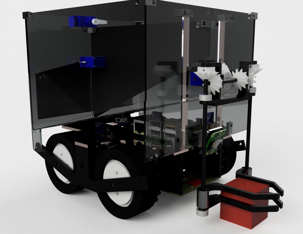
Redesigned robot
Rather than a single big 3d printed base, we have split it up into 4 plates to be connected by copper stands. We would also have a “base plate” across these 4 plates where our electronics and other mechanisms would be mounted upon. All these are quite difficult to show and explain, but more photos will be shared when we finish assembling the robot.
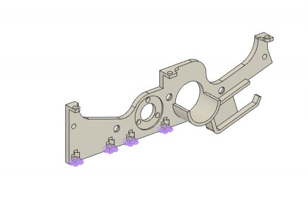
One of the 4 plates
Evacuation zone ball collection
For the evacuation zone victims, we considered many different types of ball collection mechanisms, including a rolling intake, a conveyor belt, or the traditional “scoop”. However, we wanted our robot to be as small and lightweight as possible, thus we decided to go with a traditional claw and pick up the balls one by one. Electrical contacts would also be taped to the claw to detect whether the victims are dead or alive.
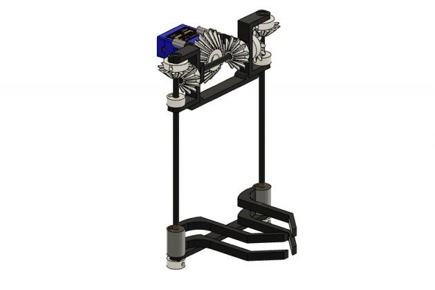
Grab and Lift mechanism
We are preparing for both 2019 and 2020 rescue line rules as we were unsure of which version our local organiser would be adhering to. Thus, we had to sort the victims before depositing. We came up with a “funnel” that would guide the victim into its own compartment depending on whether it was dead or alive.
To dispense the victims, we wanted to use 1 servo motor but be able to separately dispense the dead and live victims. Thus we have decided to use a “wiper” to open each compartment separately.
Since we need to prepare for both the 2019 and 2020 rules, we also need to ensure our compartment is large enough to fit around 6+ balls for the 2019 rules, and be able to dispense the rescue kit for the 2020 rules. In order to hold that many balls our ramp inside the compartment cannot be too steep, however to dispense the rescue kit the ramp needs to be steep enough since it’s a cube with a lot of friction. Thus, we have decided to make an “angler” which varies the angle of the ramp as well as the compartment size.
Electronics and programming
In order to sense and track the line, we have made our own light sensor array PCBs. These contain 12 LEDs, ALS-PT19 phototransistors, and 2 TCS3200 color sensors, together with a STM32F103 processor which reads and processes these sensors, then sends the data over UART or I2C to a main controller.
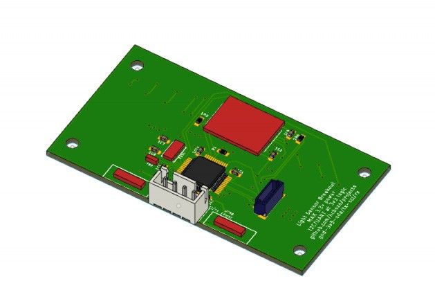
Top of the Light Sensor PCB
We haven’t started programming the robot yet, but we are planning to use 2 of these PCBs to speed up our line tracking. Details of the exact logic will be finalised when we finish building and start programming our robot.
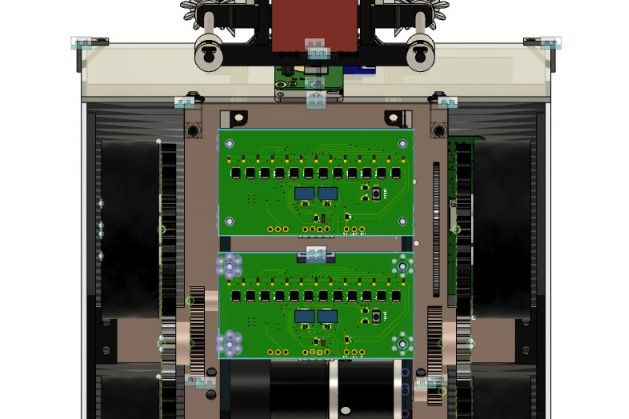
Bottom of the light sensor PCB, as seen from under the robot
In order to detect the victims in the evacuation zone as well as the rescue kit, we are planning to use a Raspberry Pi Camera with some color tracking / edge detection algorithms to speed up our runs and prevent our robot from “brute forcing”.
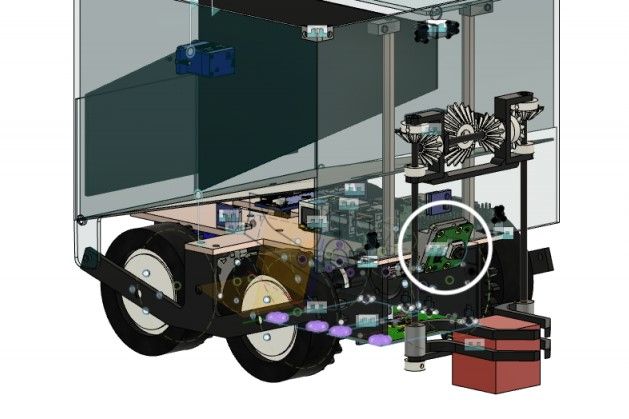
I spy with my little eye...
However, vision detection and computer vision takes a long time to tune and program. Thus, we have backup plans in our small VL53L0X distance sensors which also help to detect obstacles. We place them one above another to help us differentiate victims from the evacuation zone walls, as well as the rescue kit from other obstacles and walls on the field.
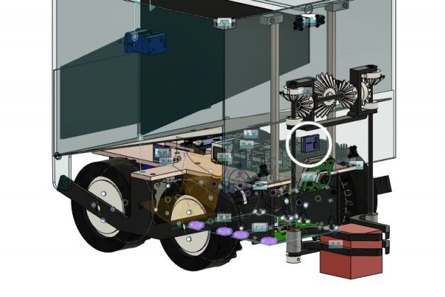
There is one more TOF sensor under the Light Sensor PCBs
Conclusion
The rescue robot is slowly coming to shape. This is a new category for us, thus progress is a little slower as we are testing a lot of new designs and ideas, resulting in many robot iterations. However we remain confident that we can build a working and competitive robot by the time the competition comes (if it isn’t cancelled…)
Do follow us on our Instagram for timely updates on our build process!
