December - Week 1
Can’t really think of a good intro like the previous post, and can’t find that many photos as well, so here is a very wordy introduction / progress update for our Rescue Line and Soccer Open robots.
Electronic Components
Since our previous robot, we have designed custom PCBs for our use, utilising different SMD ICs. However, not all of the different circuits worked as expected, and we ended up reverting to some through hole pre-made modules such as for our step-down and boost circuits.

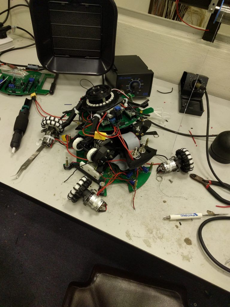
Look at the step down module on the top layer!
This year, in a bid to make our design smaller and fit within the future 20cm diameter size limit, we needed to decrease the amount of these modules used and try to integrate everything into our PCB. These component selections were a result of our previous year’s experience and extensive research into potential alternatives.
Microcontrollers
We will continue to use a Teensy 3.5/3.6 as our main processor as well as a Raspberry Pi + Raspi Camera combo for ball detection. However, for a secondary processor doing tasks such as pinging our distance sensors, we have changed from an Arduino Nano to a Maple Mini in our previous robots. This year, we are trying to embed a STM32F103 IC directly into our PCB, thus saving a lot of space previously used for pins. Once we have tested and programmed our STM32 circuit, we are planning on using many of these throughout our robot, one on each layer in order to decrease the amount of wires running up and down our robot. This also frees up valuable processing power on our main processor for potentially more complex strategies and localisation algorithms. We are testing SWD for use with our STM32 rather than programming through USB like we used to. We are also testing SPI for communication with our main controller, however it has been problematic so far and we are probably reverting to UART (since there are 6 UART on the Teensy anyways). I2C proved to be too unreliable and affected by noise for us to use.
Motor Drivers
Our robot would be powered by ST VNH5019 motor drivers, these were cheap and reliable as we have used them for our previous robot. We had considered using the smaller VNH5050 motor drivers, also made by ST, however we could not get the voltage output to scale with our PWM input and thus decided to go with the slightly bigger VNH5019.
Light Sensors
For out detection, we went with SMD LEDs and the TEMT6000 SMD Phototransistors. We would be using 48 of these together with 3 CD74HC4067 multiplexer ICs.
Mouse Sensor
We briefly experimented with a PMW3360 Mouse Sensor for localisation in our robot, however that was short-lived as we blew both the sensors we bought due to the low operating voltages. We did think about other mouse sensors such as those from Avago however online reviews showed that the PMW3360 was more accurate. We also considered a PMW3901 optical flow sensor, but it needed to be positioned at least 8cm from the ground and we did not have the space to create a 8cm high hole in our robot. This year, hopefully we can get the PMW3360 to work!
Distance Sensors
We went from using SR04 ultrasonic sensors to a VL53L0X last year. However, we faced problems getting the VL53L0X sensors we had to change I2C addresses so that we could access more than 1, thus this year we are changing to the upgraded VL53L1X TOF sensor.
IMU
We have had very bad experiences with various IMUs before, starting out with a Robot Electronics CMPS11 which couldn’t calibrate properly and randomly stopped working, then moving on to the MPU9250, Pololu MinIMU-9 and AltIMU-10, and finally the BNO055. However, while the BNO055 worked perfectly while testing, in 2 separate competitions (2018 Robocup Canada and 2019 Robocup Singapore) it failed to work well, going from bad readings to hanging the whole robot and not responding. We have also tried the Adafruit Precision NXP IMU, and while it worked really well in the example code, running the filter code together with our main code did not work very well. This year, we are experimenting with putting the BNO055 on its own I2C line and attached to its own separate microcontroller, as well as Adafruit’s IMU with its own separate microcontroller to process and filter the data.
Power
For our previous robot, we used a TPS5450 for our 3.3v output, a LM2596 (on a module) for our 5v output and a LM2587 (on a module) for our 60v solenoid output. However, the TPS5450 ran pretty hot last year, and the LM2596 module was quite huge. We would be conducting some load and efficiency tests to determine whether we should change the TPS5450 to a more efficient IC, and we would also be integrating our 5v and 60v supply into our PCB with a TPS5430 and LM2587.
Others
We are using a HC05 Bluetooth module for communication between robots and debug purposes and a Neopixel ring which lights up which direction the ball / goal is in.
Rescue Line components
We are experimenting with TCS3200 and TCS34725 color sensors to detect the green square. On one hand, the TCS3200 requires a lot of digital ports and computationally expensive pulseIn() commands to get the readings, however the TCS34725 requires an I2C multiplexer since its I2C addressed cannot be changed (to my knowledge). We are also using a DRV8833 Dual Motor Driver IC to power our 2 (old) Faulhaber 2224 motors. We chose this over the popular TB6612 since it has over-current protection, and we don’t need the higher input voltage since we are running on a 2S 7.2V battery for rescue line. Lastly, for our light sensors we would be using the same TEMT6000 in our Soccer robots. However, to interface our light sensors with our main processor, we would have a STM32 on each light sensor board and use SPI between them since there are limited UART interfaces in the STM32F103.
Oops, that was a little too wordy…
Rescue Line Robot Base
If it is not obvious from the above, my main expertise is in electronics and I have not dabbled too much with 3D CAD designing in the past. However, now I need to design an entire robot on my own (with DY but he also doesn’t really know 3D CAD yay!). In order to design this I have went from Fusion 360 to Autocad and back to Fusion 360 again, and realised that my workflow was completely wrong and messy, and now I am redoing the whole design. Great times! 🙂
However, I have managed to kind-of come up with a base design with my ghetto designing skills:
But unexperienced me decided to make the entire base one solid 3d printed chunk rather than split it up, and thus used up 100g of filament in one shot!!! Nevermind, at least it works.
Redesign coming right up but not before my test PCB is complete…
Conclusion
Most of my time last year was spent on FLL so the PCB was completed only like 2 weeks before the competition… Lets just hope that with no FLL this year it can be completed a little earlier!
Also, github.com/hcbozo
