A January Commentary
January is here, with eyes that keenly glow, A frost-mailed warrior striding a shadowy steed of snow.
Edgar Fawcett
Opening thoughts…
January is ironic. As the first month of the year, it is supposed to represent a new beginning, another reset button to try it all over again and thus, a hope for a better future. Yet, when one takes a step outside, it reflects a completely different message. Being right in the middle of the winter season, a thick blanket of snow covers every part of nature, creating a blindingly white landscape. The air is frigid, biting any exposed skin even in the slightest breeze. Trees sway slowly in the cold wind with their thin, naked branches, as if they are crying for help. Silence permeates the still, lifeless environment as most animals remain hunkered down in hibernation.

Winter Landscape by Caspar David Fredrich (1811)
However, despite this bleak scenery, we can still appreciate the significance of January if we look through the lens of ancient Roman mythology. January is named after the Roman god Janus, whom was the god of beginnings and endings, i.e. transitions. January itself is a time of transition from the old year to the new one, and times will always get tough during transitions, but the most important thing is to learn from the past and look forward to the future, no matter how dismal it may seem. In fact, Janus is usually depicted as having two faces since he looks to the past and the future, which is why he is also responsible for change and time itself.
Time (or more precisely, the race against it), was a key part of our journey in January, especially with the school term starting again. Despite an increased workload, we still kept to our schedules and made great progress. This is our lengthiest consolidation post yet, but oh well, here are some of our major accomplishments this month.
Dribbler
The previous design faced a problem of the ball “repelling” from the dribbler when it entered the catchment area. This was due to the fact that when the ball was dribbled, it would move backwards with a lot of force (especially considering how our dribbler spins the ball at 2000 RPM). The ball would hit the back wall which produces an equal reaction force that pushes the ball directly out of the dribbler. We did not face this problem in previous years because we never made our dribbler spin the ball so quickly before… 🙃
This dribbler has an auto-kick function 🤔
To fix this, a ramp was created on the bottom part of the catchment area, thus redirecting most of the backwards force of the ball diagonally upwards. This not only stopped the ball from bouncing out of the dribbler, but it also improved the dribbler’s performance since most of the backwards force of the ball was used to push itself up into the dribbler, which increased the rollers’ grip on the ball.
Oddly satisfying...
Mirror (Lightweight)
Very little has been revealed of our Soccer Lightweight robot’s actual design so far because we are experimenting with many new mechanics right now. We will definitely go into more detail when it gets closer to the competition after everything is finalised. However, all that needs to be known for now is that there will be a dribbler, a kicker, 4 motors and a 360 degree camera all somehow within that pesky 1.1kg limit 😉.
For the mirror, we cannot simply use the metal mirror of our Open robot due to weight constraints. Hence, we will be using the old method of molding mirror sheets instead, using the metal mirror as a mold. However, a big problem we faced with this method in the past was the mirror not being centralised since there was much room for error, be it during molding, cutting or gluing of the mirror sheet.
To fix this, an enclosure was made using scrap Vex channels to keep the mirror sheet aligned with the mirror mold. An M3 hole is drilled into the centre of the mirror sheet using a Vex channel for alignment before being heated and molded. This 3mm hole is used to screw the molded mirror in to our 3D printed mirror stand, which connects directly to the mirror plate. By screwing the mirror in place, instead of gluing it like we did in the past, the mirror is guaranteed to be in the centre of the robot, plus the screw head acts as a “crosshair” for the mirror’s centre when calibrating the image’s centre point!
However, during our first try, the M3 hole was enlarged and warped slightly after molding. To fix this, we will try drilling the hole after making the mirror by using a 3D printed mold of the mirror as an alignment tool. The mirror sheet also tore, likely due to too much stretching during molding. Hence, we will try giving the sheet a little slack when screwing it on next time. We will also try using an actual heat gun, which heats up a larger area, so that the heating will be more even.
Despite these problems, the mirror surface itself produced a higher quality image as compared to our past molded mirrors since now the mirror mold is metal instead of 3D printed plastic, which meant the mirror sheet could be heated to a much higher temperature before molding.
PCBs (Lightweight)
There are 4 main layers in our Soccer Lightweight robot. The first layer is at the base and is the most complex plate since it has to hold many large components while having very limited space. Hence, all the components are placed in an extremely compact layout, even the battery slots in perfectly from the back to connect directly to the first layer.
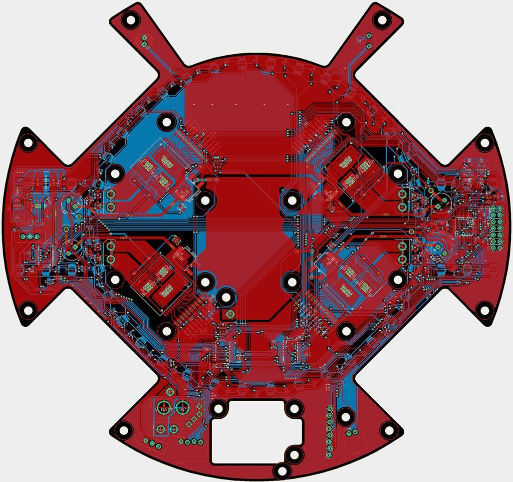
Top view of 1st layer as seen from EAGLE
On the underside of this plate, we have our 48 light sensors, 36 of which are arranged in a ring of a 64mm radius (a huge improvement compared to our ring’s radius last year of only 40+mm), while the remaining 12 are placed in a 2x3 grid on the left and right. No other components are placed on the underside to prevent cases of accidental damage when the robot is moved around.
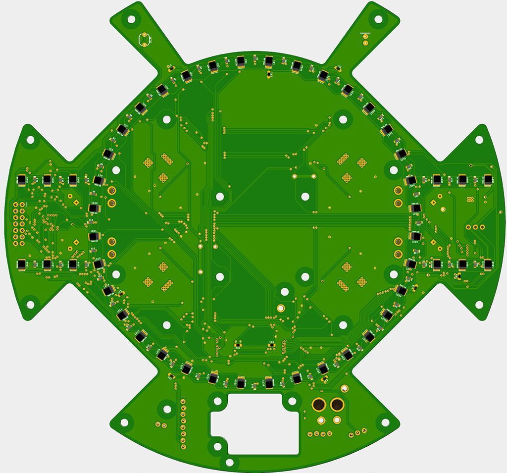
Bottom view of 1st layer as seen from Fusion 360
The second layer is much emptier since its main job is just to support the dribbler and kicker, and hence large holes are also cut where possible in order to save weight. The main component it holds is the 5V buck converter.
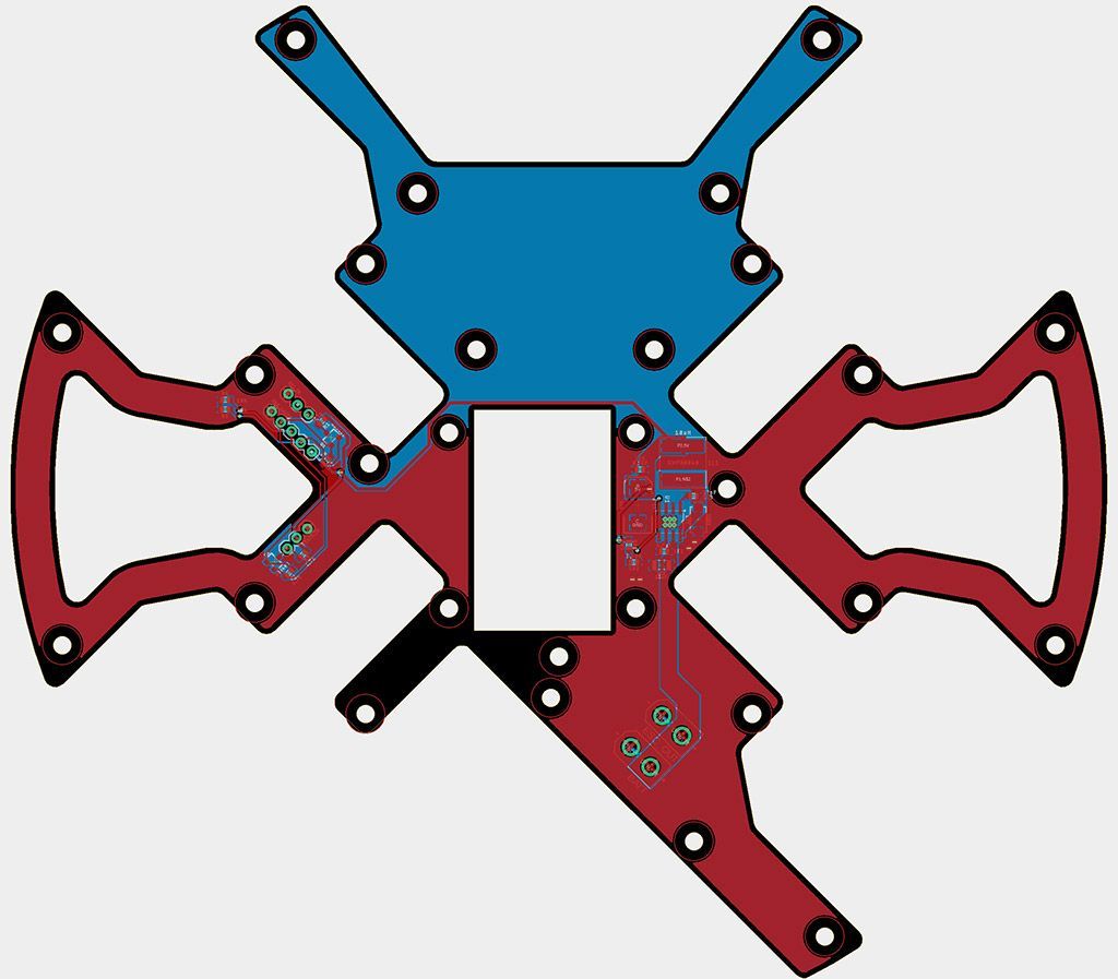
Does this 2nd layer even exist?
Meanwhile, the third layer (which is still a work in progress), will contain sensors such as the IR ring, Bluetooth module, camera, as well as our micro-controllers like the Teensy and STM32. The final layer is placed very high, above the mirror, and it holds the TOF sensors and compass. This allows the TOF sensors to sense over the goals, while keeping the compass as far away from the motors as possible.
PCBs (Open)
Our Soccer Open robot has 4 main layers, of which 3 are PCBs. The first PCB is the base layer and will be slightly similar to our Lightweight robot’s first layer since they have similar outlines, motor driver placements and light sensor positions. However, there are additional components such as the boost converter for our solenoid and other all-round different arrangements of parts to fit our robot’s design.
The second PCB is actually on the third layer (the second layer is just a carbon fibre plate since all its space is occupied) and is the main PCB holding all the microcontrollers including the Raspberry Pi, Teensy, STM32s and also the remaining sensors like the compass and Bluetooth module. The battery (which lies on the second layer) is also plugged in to this layer.
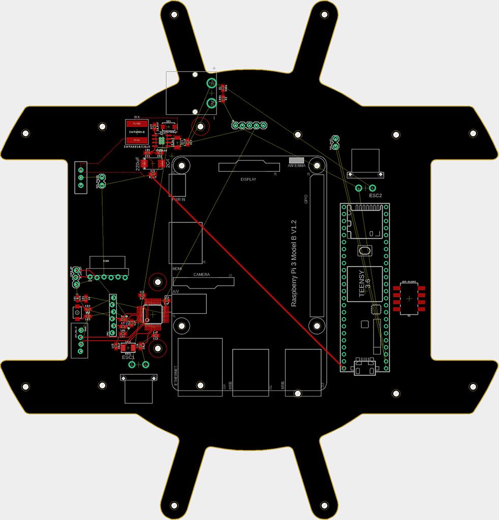
3rd layer; a work in progress
The final PCB is just above the third layer and it holds the Pi camera as well as the TOF sensors. It has an STM32 to process the TOF sensor readings as well as to control the 16 Neopixel LEDs on it that are used for debugging purposes.
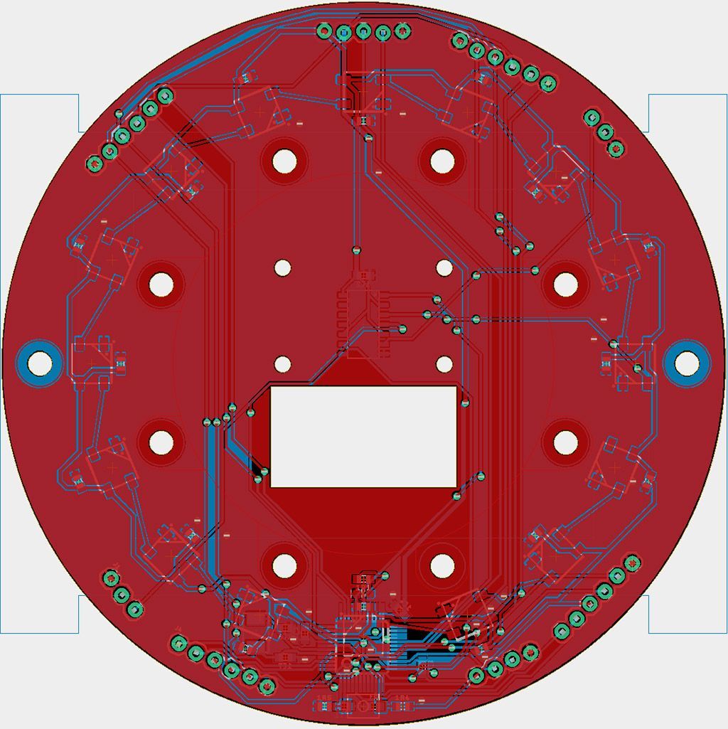
Top view of 4th layer as seen from EAGLE
In all, we should be able to finish designing our Open and Lightweight PCBs and sending them to be fabricated by the first week of February.
GUI
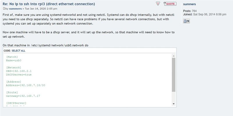
We made the amazing discovery that, for the whole of December working on the GUI for our Pi camera, when we were connecting to the Raspberry Pi from the laptop via SSH, it was connecting over WiFi instead of through a direct Ethernet connection 😂😂😂, which explained why the GUI’s video feed had such a low FPS.
However, the Raspberry Pi needed to act as a server and assign an IP address to the laptop in order for the laptop to connect through Ethernet, which we faced problems doing. Luckily, with help from the Arch Linux ARM forum, we were able to figure that out and can now connect to the Raspberry Pi directly over Ethernet.
Camera
In previous years, we have been using Python OpenCV to program our Pi camera, which came at the cost of speed. Due to Python’s Global Interpreter Lock (GIL), multi threading was not possible, and all the Python threading library was doing was simply switching between different threads rapidly instead of actually running tasks in parallel. Moreover, many basic functions like loops are significantly slower in Python than C++. Hence, we have decided to switch to programming both our camera and GUI on C++.
We initially created a program to simply capture frames from the camera to push it to its limits and we realised it was able to capture 640 by 480 images at 120 FPS! However, after adding a few basic OpenCV functions such as cvtColor (converting the image’s colour space), inRange and clone, we were surprised at how slow they were running. cvtColor itself took around 10ms, so one can just imagine how much longer more complicated functions like findContours would take.
That was when we realised our installation of OpenCV was not optimised. We enabled NEON (optimisation for ARM devices) and VFPV3 (floating point optimisation) in our CMake config before rebuilding and reinstalling OpenCV on our Raspberry Pi. With our new, optimised OpenCV library, the speed of the functions improved by a large margin; the cvtColor function can now run below 2.5ms. Our target will be to process the frames at 50 FPS, which gives us about 20ms to process each frame.
Also, to finally stop our rampant spaghetti coding practices and start going “professional”, we will use classes to make our code more readable… 🙃
Conclusion
To be honest, January was a solid “meh”; we have definitely made progress but things seem like they can go much faster than this. Maybe its just the low after the New Year’s high I’m feeling here, or maybe our gears need time to be oiled up before going into overdrive… who knows? Personally, I would say I am entering February with a feeling of optimistic apprehension; optimism stemming from the hope that these robots could very well be the best robots in the history of our team, but apprehension stemming from the cognizance of the multitude of ways we could all fail spectacularly, especially when considering past experiences. But then again, maybe I worry too much… 🤷
What I do know for sure is that February is going to be our make-it-or-break-it month. As long as we finish construction of our robots by the end of February, all should be well… 🤞
